
Circular Polarization Analysis
To verify the antenna’s circular polarization performance, the radiated electric field is simulated (see Figure 6). In a Cartesian coordinate system, the far-field electric field is decomposed into two orthogonal components in the x- and y-directions, denoted as Ex and Ey, respectively. Ideal circular polarization requires |Ex| = |Ey| and the phase difference Δφ = Ey - Ex = ± 90 degrees. In engineering practice, circular polarization is deemed achieved when the amplitude difference |Ex| - |Ey|| ≤ 3 dB and the phase difference |Δφ - 90| ≤ 15 degrees. Figure 6a shows that the frequency range where |Ex| - |Ey| ≤ 3 dB (the purple shaded area) is between 3.21 and 4.58 GHz. Figure 6b shows that the frequency band where |Δφ - 90| ≤ 15 degrees is from 4.1 to 4.5 GHz.
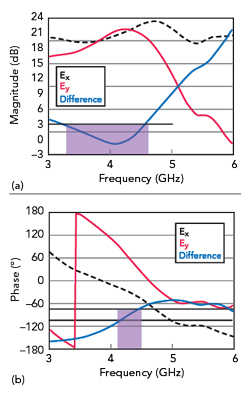
Figure 6 Simulated magnitude ratio and phase difference in the orthogonal x- and y-components of the radiated electric field.
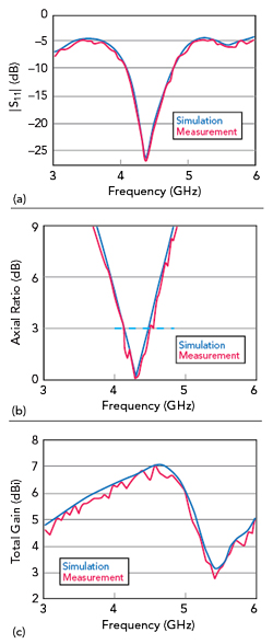
Figure 7 Simulated and measured antenna |S11| (a), AR (b) and total gain (c).
SIMULATIONS AND MEASUREMENTS
To validate the design, a prototype antenna is characterized. Measurements are performed using a vector network analyzer and an anechoic chamber (see Figures 7 and 8). As shown in Figure 7a, the measured impedance bandwidth spans 4.07 to 4.77 GHz, exhibiting a slight upward frequency shift compared to simulations while maintaining overall consistency. Figure 7b shows a measured minimum AR of 0.2 dB with a 3 dB AR bandwidth of 370 MHz from 4.12 to 4.49 GHz, aligning closely with simulated predictions. The measured gain in the main beam (see Figure 7c) shows a slight reduction relative to the simulation, yet achieves a peak value of 7.05 dBi, consistent with the simulated value of 7.06 dBi.
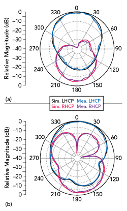
Figure 8 Simulated and measured normalized radiation patterns at 4.3 GHz: xoz plane (a) and yoz plane (b).
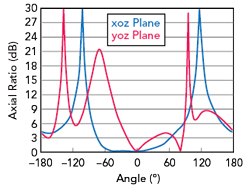
Figure 9 Axial ratio versus angle at 4.3 GHz.
Measured radiation patterns at 4.3 GHz exhibit good symmetry, with the cross-polarization level within the main beam region below -40 dB. The 3 dB beamwidths in the E- and H-planes are approximately 65.32 degrees (from -33.39 to 31.93 degrees) and 89.74 degrees (from -44.87 to 44.87) degrees, respectively, demonstrating excellent broadside CP radiation characteristics. Notably, the back lobe level is below -20 dB, enhancing forward directivity. A close agreement between simulated and measured results is observed.
Results of simulations performed to analyze the angular variation of the AR at 4.3 GHz are shown in Figure 9. The 3 dB AR angle ranges in the H-plane are -75 to 63 degrees, and in the E-plane, they are -20 to 30 degrees and 60 to 85 degrees. In the E-plane, the AR exceeds 3 dB slightly between 30 and 60 degrees. The discontinuity in the 3 dB AR angular range is likely attributed to alterations in the current path introduced by the slot. To improve angular continuity, attempts were made to smooth the diamond-shaped slot angles; however, this adjustment was found to adversely affect the circular polarization performance of the main beam. Therefore, the current design represents the optimal compromise under these constraints. In subsequent work, it is planned to incorporate additional MS elements to achieve more refined control over both amplitude and phase, with the aim of resolving this issue.
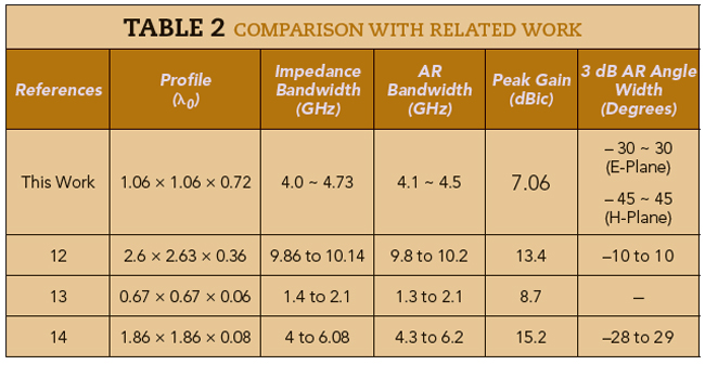
Table 2 compares the profile and performance of this with other related works. This antenna exhibits favorable radiation properties, including a wide CP bandwidth and a wide 3 dB AR angle in a compact size.
CONCLUSION
A corner-truncated rectangular slot antenna incorporates an MS superstrate. Through optimization of its corner truncation parameters, effective excitation and separation of orthogonal TM10 and TM01 modes are achieved. An MS structure is employed to manipulate surface current distributions, leading to significant improvement in the antenna’s circular polarization performance. Experimental results indicate that the minimum AR of the improved antenna is reduced to as low as 0.14 dB, approximating ideal circular polarization. The impedance bandwidth is extended to 730 MHz (from 4.0 to 4.73 GHz), the 3 dB AR bandwidth is 400 MHz (from 4.1 to 4.5 GHz) and the peak gain is 7 dBi. Its radiation pattern exhibits stable broadside right-hand circular polarization characteristics. Owing to its superior radiation performance, this antenna is suitable for use in high-quality C-Band communication systems.
References
- K. Li, Y. Liu, Y. Jia and Y. J. Guo, “A Circularly Polarized High Gain Antenna with Low RCS Over a Wideband Using Chessboard Polarization Conversion Metasurfaces,” IEEE Transactions on Antennas and Propagation, Vol. 65, No. 8, August 2017, pp. 4288–4292.
- H. -X. Xu, Y. Shao, H. Luo, Y. Wang and C. Wang, “Janus Reflective Polarization-Division Metadevices with Versatile Functions,” IEEE Transactions on Microwave Theory and Techniques, Vol. 71, No. 8, August 2023, pp. 3273–3283.
- H. Tran-Huy, H. -H. Nguyen and T. Hoang Thi Phuong, “A Compact Metasurface-Based Circularly Polarized Antenna for RFID Readers,” PLOS.One, Vol. 18, No. 8, August 2023, Web. https://doi.org/10.1371/journal.pone.0288334.
- S. Yang, Z. Yan, M. Cai and X. Li, “Low-Profile Dual-Band Circularly Polarized Antenna Combining Transmitarray and Reflectarray,” IEEE Transactions on Antennas and Propagation, Vol. 70, No. 7, July 2022, pp. 5983–5991.
- Z. Chen, W. Feng, Y. You, Y. Yu, D. Guan, L. Sun, Y. Hu and Y. Lu, “Low-Profile All-Metal Dual-Band Dual-Polarized Shared-Aperture Phased Arrays for UAV Applications,” IEEE Internet of Things Journal, Vol. 12, No. 15, August 2025, pp. 31466–31476.
- R. Garg, P. Bhartia, I. Bahl and A. Ittipiboon, “Microstrip Antenna Design Handbook,” Artech House, Norwood, Mass., 2001.
- N. Yu, P. Genevet, M. A. Kats, F. Aieta, J. -P. Tetienne, F. Capasso and Z. Gaburro, “Light Propagation with Phase Discontinuities,” Science, Vol. 334, No. 6054, September 2011, pp. 333–337.
- S. B. Glybovski, S. A. Tretyakov, P. A. Belov, Y. S. Kivshar and C. R. Simovski, “Metasurfaces: From Microwaves to Visible,” Physics Reports, Vol. 634, May 2016, pp. 1–72.
- Z. N. Chen, T. Li and W. E. I. Liu “Microwave Metasurface-Based Lens Antennas for 5G and Beyond,” 14th European Conference on Antennas and Propagation, March 2020.
- K. E. Kedze, H. Wang and I. Park, “A Metasurface-Based Wide-Bandwidth Circularly Polarized Patch Antenna,” IEEE Transactions on Antennas and Propagation, Vol. 70, No. 1, January 2022, pp. 732–737.
- X. Gao, L. Y. He, S. J. Yin, C. H. Xue, G. F. Wang, X. M. Xie, H. Xiong, Q. Cheng and T. J. Cui, “Ultra-Wideband Low-RCS Circularly Polarized Antennas by Metasurfaces,” IEEE Transactions on Antennas and Propagation, Vol. 72, No. 2, February 2024, pp. 1999–2006.
- G. Gao, R. -F. Zhang, W. -F. Geng, H. -J. Meng and B. Hu, “Characteristic Mode Analysis of a Nonuniform Metasurface Antenna for Wearable Applications,” IEEE Antennas and Wireless Propagation Letters, Vol. 19, No. 8, August 2020, pp. 1355–1359.
- J. Cui, X. Zhao and W. Sheng, “Low Profile and Broadband Circularly Polarized Metasurface Antenna Based on Nonuniform Array,” AEU-International Journal of Electronics and Communications, Vol. 156, November 2022.
- Q. Chen, J. Yang, C. He, L. Hong, D. Zhang, S. Huang, F. Yu, L. Zhang, W. Xiong and H. Zhang, “Nonuniform Metasurface for Wideband Circularly Polarized Antenna Using Characteristic Mode Analysis,” AEU-International Journal of Electronics and Communications, Vol. 172, No. 8, December 2023.