
A corner-truncated slot antenna structure loaded with a rectangular metasurface (MS) superstrate addresses the insufficient circular polarization axial ratio performance and narrow operating bandwidth of conventional microstrip patch antennas. The radiating element is a corner-truncated rectangular slot patch with a microstrip line-coupled feed, where orthogonal TM10 and TM01 modes are excited through optimized corner truncation dimensions. To improve circular polarization performance, a rectangular patch MS superstrate is integrated with the baseline antenna. The minimum axial ratio (AR) is 0.14 dB (approaching ideal circular polarization) with a -10 dB impedance bandwidth of 730 MHz (from 4.0 to 4.73 GHz), a 3 dB AR bandwidth of 400 MHz (from 4.1 to 4.5 GHz) and a peak gain of 7 dBi. Stable circular polarization characteristics are observed in far-field radiation patterns.
With the rapid development of wireless technology, C-Band (4 to 8 GHz) has been widely used in satellite communications, radar systems and 5G networks due to moderate propagation characteristics and spectral resources.1,2 Circularly polarized (CP) antennas, recognized for their strong resistance to multipath interference and flexible polarization matching capabilities, have become one of the core components in such systems.3
However, conventional microstrip CP patch antennas exhibit insufficient AR performance and narrow impedance bandwidth, making them inadequate for modern communication systems requiring high stability and broadband operation.4,5 Existing design improvements (e.g., multilayer stacking and slot loading) can partially enhance performance but often lead to structural complexity or increased dimensions, thereby limiting practical applications.6,7
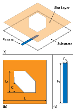
Figure 1 Baseline antenna 3D view (a), corner-cut square slot layer (b) and feed (c).
To overcome these challenges, MS technology, leveraging its precise control over electromagnetic wave amplitude and phase, has been widely applied to antenna design in recent years.8,9 Nevertheless, current MS-based CP antennas predominantly adopt symmetric unit structures with limited efficiency in the collaborative excitation and regulation of orthogonal modes, while the co-optimization of AR and impedance bandwidths remains challenging.10,11
To address these issues, this article describes a corner-truncated CP slot antenna structure loaded with a rectangular MS superstrate to achieve performance breakthroughs with an asymmetric design and multi-mode synergy. The key innovations include: 1) adoption of a corner-truncated rectangular slot as the radiating element, enabling separation of orthogonal TM10 and TM01 modes through optimized asymmetric truncation, 2) introduction of a rectangular patch MS superstrate to regulate surface current distribution and optimize the amplitude-phase relationship of the orthogonal modes and 3) co-design of the MS and baseline antenna to achieve expansion of both the impedance and AR bandwidths.
ANTENNA DESIGN
Antenna Configuration and Analysis
The baseline antenna adopts a corner-truncated rectangular slot structure with a microstrip line-coupled feed (see Figure 1). It is fabricated on a 50 × 50 mm2 Rogers 5880 substrate (εr = 2.2, tan δ = 0.0014), with the corner-truncated slot layer and feed layer located on opposite sides.
Asymmetric corner truncation breaks structural symmetry, separating the resonant frequencies of the orthogonal TM10 and TM01 modes.
Through optimized truncation dimensions, the amplitudes of the two modes are equalized, and a 90-degree phase difference is established to enable CP radiation. Iterative parameter optimization in HFSS 15 electromagnetic simulation software yields the baseline antenna performance shown in Figure 2 (without the MS superstrate).
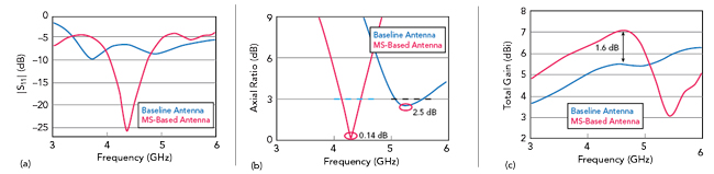
Figure 2 Simulation of |S11| (a), axial ratio (b) and total gain in the main lobe (c) for the baseline and the MS-based antennas.
The baseline antenna design exhibits two resonances, including one at 3.73 GHz (|S11| = -9.5 dB) and one at 4.89 GHz (|S11| = -8.45 dB). Both are greater than -10 dB, indicating suboptimal impedance matching (see Figure 2a). The AR curve in Figure 2b shows a single minimum of 2.5 dB at 5.27 GHz, suggesting insufficient CP performance due to incomplete fulfillment of amplitude-phase requirements for orthogonal modes. The gain curve in Figure 2c shows a gradual increase in gain with frequency but is relatively flat between 4.31 and 5.05 GHz. The average gain from 3 to 6 GHz is 5.26 dBi.
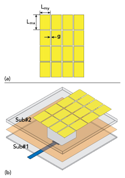
Figure 3 MS superstrate with symmetric rectangular unit cells (a) and MS-based antenna 3D view (b).
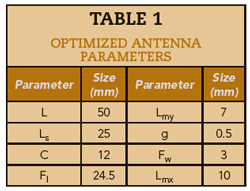

Figure 4 MS superstrate with symmetric (square-shaped) unit cells.
A rectangular patch MS superstrate is integrated directly on the baseline antenna with no air gap between the MS layer and the antenna (see Figure 3). Departing from conventional corner-truncated MS designs, this work employs asymmetric rectangular MS units that synergize with the feed structure to enable multi-mode collaboration and precise regulation of orthogonal modes. Critical parameters of both the MS superstrate and the baseline antenna are iteratively optimized in HFSS 15, yielding the improved performance shown in Figure 2. Final antenna dimensions are summarized in Table 1.
Post-optimization results demonstrate a significant reflection coefficient improvement (see Figure 2a) featuring a distinct resonance at 4.35 GHz with a depth of 26.5 dB, indicating robust impedance matching. The -10 dB impedance bandwidth is 17.6 percent from 4 to 4.73 GHz. A minimum AR of 0.14 dB is obtained at 4.31 GHz (see Figure 2b), shifted lower in frequency compared with the baseline. The 3 dB AR bandwidth is 9.3 percent (from 4.1 to 4.5 GHz) and is fully contained within the impedance bandwidth. The simulated peak gain of 7.06 dBi at 4.58 GHz is a 1.65 dB improvement over the baseline (see Figure 2c). Within the CP bandwidth, the peak gain is 7.01 dBi.
To clarify the MS superstrate design approach, antenna performance is analyzed using both symmetric (see Figure 4) and asymmetric (see Figure 3) unit cells, specifically square (MS-A) and rectangular (MS-B) configurations, to illustrate the advantage of using asymmetric unit cells. The impedance bandwidths are comparable, while the MS-B configuration shifts the center frequency higher with a deeper |S11| minimum (see Figure 5a). The MS-A antenna yields an optimized AR of 2.6 dB at 3.9 GHz within a narrow 100 MHz AR bandwidth, while the MS-B antenna yields a minimum AR of 0.14 dB with a 370 MHz AR bandwidth (see Figure 5b). Gain patterns are similar (see Figure 5c). The MS-A configuration shows a 0.3 dB higher peak due to its enlarged radiating aperture, which enhances main beam efficiency.
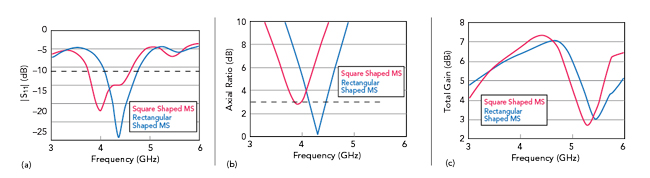
Figure 5 Simulated performance of MS-based antennas with different unit cells: |S11| (a), AR (b) and total gain (c).