

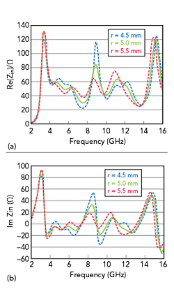
Figure 4 Input impedance as a function of r: real (a) and imaginary (b).
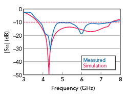
Figure 5 Measured and simulated reference antenna |S11|.
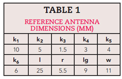
The curved portion of the feedline provides current to the radiators. Further simulation shows the input impedance also depends on the radius r (see Figure 4). By optimizing the values of lg and r, making Re (Zin) close to 50 Ω and Im (Zin) near 0 Ω, |S11| < 10 dB can be achieved over a wide frequency range from 3.8 to 7.5 GHz (see Figure 5). Measurements of a prototype antenna built on an FR4 substrate (εr = 4.4) agree well with the simulation. Optimized antenna parameters are listed in Table 1.
AMC-Backed Antenna
Although the reference antenna has a wide impedance bandwidth, the reduced area of the ground causes bidirectional radiation, resulting in low directivity in the forward radiation. The multilayer AMC structure acts as a reflector to improve radiation performance (see Figure 6a). The distance between the reference antenna and the top layer of the multilayer AMC structure is denoted as h2. Antenna impedance bandwidth is primarily affected by h2 (see Figure 6b). A value of h2 = 9 mm is chosen so that the in-phase reflection band corresponds with the operating band to the greatest extent. This is the frequency range from 4.5 to 7.5 GHz.
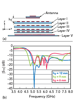
Figure 6 Lateral view of the antenna and multilayer AMC structure (a) and simulated |S11| as a function of h2 (b).
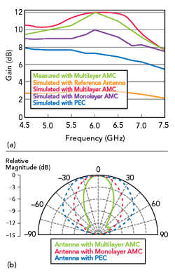
Figure 7 Simulated and measured antenna gain (a) and simulated E-plane radiation patterns at 6 GHz (b) with different reflectors.
To assess the influence of the multilayer AMC structure on antenna radiation performance more intuitively, gain is simulated with three different reflectors, including a PEC, monolayer AMC and multilayer AMC for comparison (see Figure 7a). For the reference antenna, the gain in the forward direction is only about 3 dBi. With the PEC, gain is significantly improved.
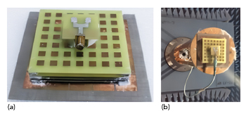
Figure 8 Photograph of the multilayer AMC antenna (a), the antenna mounted in an anechoic chamber for test (b).
With the monolayer AMC structure, the simulated gain is improved by approximately 1 to 2 dB compared to the PEC reflector. This is attributed to the in-phase reflection characteristics of the AMC structure. In addition, an array-like effect caused by the cells of the AMC structure, which can be considered as sub-radiators, also helps to improve antenna system gain.
With the multilayer AMC structure, gain is further increased. The incremental improvement is up to 3 dB with a maximum gain of 12 dBi. This is mainly attributed to a flatter in-phase reflection characteristic. Additionally, for the monolayer AMC structure, the thickness of the substrate is 13.6 mm, while for the multilayer AMC structure, the thicknesses of the five plates are 1 mm, 1 mm, 0.8 mm, 0.8 mm and 0.8 mm, respectively. This results in lower substrate loss and higher gain. Gain of the multilayer AMC antenna is measured as well (see Figure 7a), demonstrating close agreement with the simulation.
Simulated E-plane radiation patterns of the antenna with different reflectors at 6 GHz (see Figure 7b) show that higher directivity with a narrower beamwidth is achieved with the multilayer AMC structure.
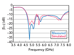
Figure 9 Simulated and measured |S11|.
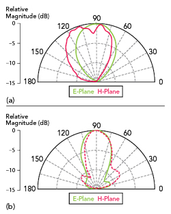
Figure 10 Measured radiation patterns at 5 (a) and 6 (b) GHz.
MEASUREMENTS
Performance of the prototype multilayer AMC-backed antenna (see Figure 8), including |S11|, gain and radiation patterns, is measured in a far-field anechoic chamber. Gain is shown in Figure 7a, |S11| is shown in Figure 9 and measured radiation patterns are shown in Figure 10. Measurements agree closely with the simulations.
CONCLUSION
A wideband and high gain antenna employs a five-layer AMC structure. The AMC acting as a ground plane is constructed by printing periodic patches on substrates with different dielectric constants to effectively broaden the frequency range of in-phase reflection. Attributing to this in-phase reflection characteristic, antenna gain from 4.5 to 7.5 GHz is significantly improved, achieving a maximum gain of 12 dBi. This wideband high gain antenna has potential communication systems applications.
ACKNOWLEDGMENT
This work was supported by the Science and Technology Research Project of Henan Science and Technology Department (Grant No: 242102210067), the Key R&D Project of Henan Province-Research and Application of Key Technology (Grant No: 241111212500) and Henan Province Key R&D and Promotion Special (Technology Tackling Key) Project (No.232102210181, No.252102521071).
References
- B. Hua, L. Han, Q. Zhu, C. -X. Wang, K. Mao, J. Bao, H. Chang and Z. Tang, “Ultra-Wideband Nonstationary Channel Modeling for UAV-to-Ground Communications,” IEEE Transactions on Wireless Communications, Vol. 24, No. 5, May 2025, pp. 4190–4204.
- A. Abbosh, “Ultra-wideband Quasi-Yagi Antenna Using Dual-Resonant Driver and Integrated Balun of Stepped Impedance Coupled Structure,” IEEE Transactions on Antennas and Propagation, Vol. 61, No. 7, July 2013, pp. 3885–3888.
- C. L. Mak, K. M. Luk, K. F. Lee and Y. L. Chow, “Experimental Study of a Microstrip Patch Antenna with an L-Shaped Probe,” IEEE Transactions on Antennas and Propagation, Vol. 48, No. 5, May 2000, pp. 777–782.
- H. -X. Xu, S. Tang, S. Ma, W. Luo, T. Cai, S. Sun, Q. He and L. Zhou, “Tunable Microwave Metasurfaces for High-Performance Operations: Dispersion Compensation and Dynamical Switch,” Scientific Reports, Vol. 6, No. 38255, November 2016.
- I. H. Abdelaziem, A. A. Ibrahim and M. A. Abdalla, “High Gain and Efficiency Dual-Band Antenna Using Meta-Surface,” AEU-International Journal of Electronics and Communications, Vol. 148, May 2022.
- M. Singh and M. S. Parihar, “High-Gain MIMO Antenna with Broad Beam Scan Range Using Anisotropic Planar Meta-Lens Array for Millimeter-Wave-Band 5G Applications,” IEEE Antennas and Wireless Propagation Letters, Vol. 24, No. 2, February 2025, pp. 324–328.
- S. Kundu and A. Chatterjee, “A Compact Super Wideband Antenna with Stable and Improved Radiation Using Super Wideband Frequency Selective Surface,” AEU-International Journal of Electronics and Communications, Vol. 150, June 2022.
- C. P. Scarborough, D. H. Werner and D. E. Wolfe, “Functionalized Metamaterials Enable Frequency and Polarization Agility in a Miniaturized Lightweight Antenna Package,” Advanced Electronic Materials, Vol. 2, No. 2, February 2016.
- Y. Jia, Y. Liu, H. Wang, K. Li and S. Gong, “Low-RCS, High-Gain and Wideband Mushroom Antenna,” IEEE Antennas and Wireless Propagation Letters, Vol. 14, October 2014, pp. 277–280.
- D. Sievenpiper, L. Zhang, R. F. J. Broas, N. G. Alexopoulos and E. Yablonovich, “High-Impedance Electromagnetic Surface with a Forbidden Frequency Band,” IEEE Transactions on Microwave Theory and Techniques, Vol. 47, No. 11, November 1999, pp. 2059–2047.
- X. Chen, Z. J. Su, L. Li and C. H. Liang, “Radiation Pattern Improvement in Closely-Packed Array Antenna by Using Mushroom-Like EBG Structure,” IET International Radar Conference, April 2013.
- L. Li, Q. Chen, Q. Yuan, C. Liang and K. Sawaya, “Surface-Wave Suppression Band Gap and Plane-Wave Reflection Phase Band of Mushroom-Like Photonic Band Gap Structures,” Journal of Applied Physics, Vol. 103, No. 2, January 2008.
- P. Chen, X. D. Yang, C. Y. Chen and Z. H. Ma, “Broadband Multilayered Array Antenna with EBG Reflector,” International Journal of Antennas and Propagation, September 2013.
- S. X. Ta and T. K. Nguyen, “AR Bandwidth and Gain Enhancements of Patch Antenna Using Single Dielectric Superstrate,” Electronics Letters, Vol. 53, No. 15, July 2017, pp. 1015–1017.
- A. A. Ibrahim and W. A. E. Ali, “High Gain, Wideband and Low Mutual Coupling AMC-Based Millimeter Wave MIMO Antenna for 5G NR Networks,” AEU-International Journal of Electronics and Communications, Vol. 142, December 2021.
- K. Agarwal, N. Nasimuddin and A. Alphones, “Wideband Circularly Polarized AMC Reflector Backed Aperture Antenna,” IEEE Transactions on Antennas and Propagation, Vol. 61, No. 3, March 2013, pp.1456–1461.
- S. Trinh-Van, O. H. Kwon, E. Jung, J. Park, B. Yu, K. Kim, J. Seo and K. C. Hwang, “A Low-Profile High-Gain and Wideband Log-Periodic Meandered Dipole Array Antenna with a Cascaded Multi-Section Artificial Magnetic Conductor Structure,” Sensors, Vol. 19, No. 20, October 2019.
- S. J. Orfanidis, “Reflection and Transmission in Electromagnetic Waves and Antennas,” Rutgers University, 2008.
- D. Feng, H. Zhai, L. Xi, S. Yang, K. Zhang and D. Yang, “A Broadband Low-Profile Circular-Polarized Antenna on an AMC Reflector,” IEEE Antennas and Wireless Propagation Letters, Vol. 16, September 2017, p. 2840–2843.
- L. Tang and Z. Zhang, “Ultrawide Bandwidth Rectangular Patch Antenna Over Artificial Magnetic Conductor,” IEEE International Conference on Microwave and Millimeter Wave Technology (ICMMT), May 2012.
- D. Sievenpiper, “High-Impedance Electromagnetic Surfaces”, Ph.D. Dissertation, Department of Electrical Engineering, UCLA, Calif., USA, 1999.
TechnicalFeature