

VECTOR PROPERTIES
To get a picture of the complete set of 3D characteristics of the crystal, it is necessary to measure the acceleration sensitivity in three orthogonal axes. Figure 4a shows a quartz crystal oscillator with a set of axes overlaid on the device. Figure 4b depicts the coordinate system that defines the magnitude and direction of the Γ vector.
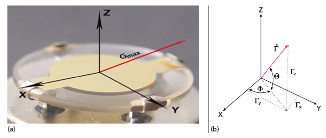
Figure 4 (a) Quartz crystal oscillator oriented on a coordinate system. (b) Coordinate system and relationships to determine maximum g-sensitivity vector.
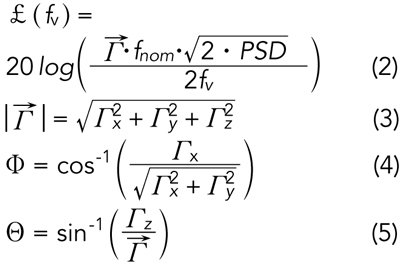
The maximum g-sensitivity vector, Γmax, usually does not align precisely with one of the measured axes relative to the crystal package. However, by using trigonometric identities, the magnitude and direction of the Γmax vector can be determined. Equations 3 through 5 show the relationships to derive the quantities necessary to determine the maximum g-sensitivity vector in Figure 4b.
The effect of changing the direction of the acceleration force is shown in Figure 5. The maximum frequency shift occurs when the acceleration force is in the same direction as the Γmax vector. As illustrated, it decreases as the cosine of α as the direction changes.
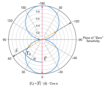
Figure 5 Acceleration sensitivity versus direction of applied force.
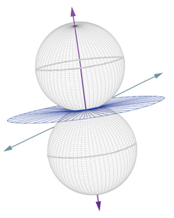
Figure 6 3D representation of acceleration sensitivity versus direction of applied force.
Figure 5 illustrates the effect in two dimensions, while Figure 6 shows how this also applies in three dimensions. Another potentially useful aspect that can be seen here is the plane of “zero sensitivity” that exists when the acceleration forces are applied in the plane that is perpendicular to the Γmax vector. If a crystal-based device in a particular system experiences vibration forces that are primarily from one direction, orienting the oscillator so that the sensitive axis is perpendicular to the force can result in a substantial reduction of the vibration-induced effects.
MITIGATION METHODS
There are also methods of compensating for the effects of vibration on a crystal oscillator. Active cancellation methods can be used that employ an accelerometer to sense the level of vibration being experienced by the crystal. This signal is then fed back to the oscillator circuit after being scaled and phase shifted properly to cancel the instantaneous frequency shift caused by the vibration.
If the magnitude and direction of the Γ vector are known, it is possible to substantially reduce the effect by using two crystals, which are positioned so that the vectors are anti-parallel, pointing in opposite directions. The two crystals are then connected electrically in either a parallel or series configuration and connected to an oscillator circuit. This type of passive compensation can reduce the effects of vibration on an oscillator substantially. Figure 7 shows the phase noise response of a conventional TCXO that achieves Γ = 2.5 ppb/g. Figure 8 shows the phase noise response of a vibration-compensated TCXO under the same vibration profile as the conventional TCXO in Figure 7. For this case, Γ = 0.02 ppb/g and the graph in Figure 8 shows a phase noise improvement of approximately 40 dB that can be achieved under random vibration conditions using this technique. This passive compensation method is being employed in miniature TCXOs to reduce the effective g-sensitivity to less than 8 × 10-11 per g.
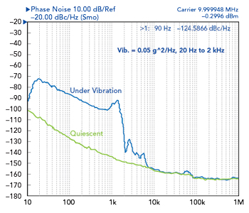
Figure 7 Conventional TCXO phase noise response.
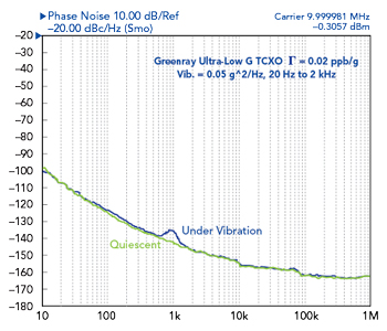
Figure 8 Vibration-compensated TCXO phase noise response.
VIBRATION ISOLATION
Another method for reducing the effects of vibration on a system is to use mechanical vibration isolation. This can be very effective at reducing the high frequency vibrational energy experienced by the component. However, the isolation is only achieved above the natural frequency of the isolator. Figure 9 shows how the effectiveness of the isolation changes relative to the natural frequency of the isolator, placing constraints on the size and weight of the components. Figure 10 shows examples of typical miniature vibration isolators. If isolation at low frequencies is needed, it is usually not practical to use mechanical isolators for components in small assemblies.
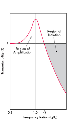
Figure 9 Transmissibility versus frequency.
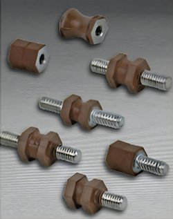
Figure 10 Typical vibration isolators.
CONCLUSION
Quartz crystal oscillators are increasingly important, fundamental building blocks in many electronic systems. Properly designed, they will provide clean, relatively noise-free frequency references in a benign environment without movement or acceleration. However, any change in position or periodic movement will shift the operating frequency of the oscillator. This article has discussed the nature and magnitude of the vibratory environment that a system may encounter. It has also provided some insights into the effects that this vibration will have on the oscillator signal, along with how those effects can be predicted and possibly mitigated to varying degrees.