MATERIAL AND CONNECTION METHOD
After experimenting with different materials, a sub-mm metal mesh conductive film was selected for its performance, reliability and transparency. The material for the housing or carrier is ABS/PC and the material for the antenna is PET. Taoglas Invisible Antenna products feature a VLT of greater than 74 percent TCF. Compare this to the automotive industry’s standards, which require a VLT of 70 percent for the front windshield. The material is also heat-resistant and UV-protected. The antennas can operate from -40°C to 85°C and can withstand a non-condensing 65°C, 95 percent relative humidity environment.
To connect to the cables, a solution was developed that involved a mechanical connection method using clips to create a consistent RF connection. This was achieved by feeding the antenna from the edge and using an invisible tail to act as a cable. Figure 3 shows the unique PCB adapter board with a FAKRA connector solution.
ENSURING OPTIMAL RF PERFORMANCE AND INTEGRATION CONSIDERATIONS
While covert, it is important to remember that transparent antennas are still antennas. Ground plane considerations are relevant and each antenna should be placed at least 20 mm from metal to maintain performance. Like other antennas, key performance metrics for transparent antennas include antenna efficiency, impedance matching, gain, radiation patterns and bandwidth coverage. Figure 4 shows the TFX62.A antenna total efficiency versus frequency when mounted on a 4 mm plastic substrate.
Taoglas has added to its Taoglas Invisible Antenna portfolio with SMA connector options. These include the TFX62.C for cellular applications, the TFX125.B for GNSS applications and the TFX257.B for Wi-Fi applications. Modular design allows for customizable MIMO configurations. The antennas can be placed orthogonally to each other to maximize coverage and throughput while minimizing coupling.
APPLICATION EXAMPLES
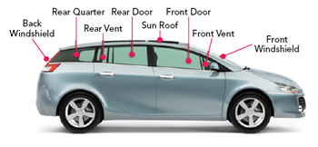
Figure 5 Glass placement options on a vehicle.1
While transparent antennas cannot match the performance of solid conductive materials like copper, they offer unique benefits. For instance, placing a cellular transparent antenna on a window provides the closest possible access to external signals, improving signal strength, coverage and data rates. In automotive applications, covertly installed transparent antennas can be placed on automotive glass in the front/rear windshield, sunroof and/or side window locations. These antennas can serve as replacements for large external antennas. Transparent antennas can enhance vehicle-to-vehicle (V2V) and vehicle-to-infrastructure (V2I) communication, enabling advanced driver-assistance systems and autonomous driving features. When used in place of external antennas, they provide cost savings and simplify the installation process, as no drilling is required and instead use a “peel and stick” adhesive. Figure 5 shows some of the areas where covert transparent antennas could be installed.
One potential application is the use of transparent antennas on vehicle glass to enable satellite communication in cars. This would provide reliable connectivity in remote areas where cellular networks are unavailable. Both established and new satellite operators are exploring how to approach the emerging satellite IoT market. Traditionally relying on proprietary protocols, satellite operators are now exploring the advantages of leveraging existing wireless IoT technologies, such as LoRaWAN, NB-IoT, LTE-M and 5G NR Low Power. Integrating these technologies can create seamless transitions from terrestrial to satellite networks, which are known as non-terrestrial networks (NTN).
This advancement of NTN brings new commercial opportunities for satellite providers, module and chipset manufacturers, along with antenna providers. The automotive industry has proposed n256 and n255 as the industry standard bands for the 5G NB-IoT and 5G NR standards. This is in line with the 3GPP Rel-17. Table 1 highlights the frequencies and regional use of these NTN bands.

It is interesting to note that band n23 is listed here for the North American region. North America represents a large market for several applications. Bands n23 should be covered in any antenna design to ensure the solution can operate in North America. Bands n23 and n256 are similar in terms of start and stop frequency for each channel. Designing for a combined n23/n256 solution would not increase the complexity of the design or the R&D development time required. Designing for a combined n23/n256 band provides more commercial opportunities.
Most of the NTN technologies currently in development are focused on IoT applications. The large latency and low throughput associated with GEO satellites currently limit the range of potential applications. As more LEO satellites come online, the potential exists for low latency, high-throughput applications in this segment.
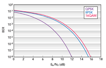
Figure 6 BER for various modulation schemes.
A link budget is required to determine whether specified antenna parameters, such as antenna gain, will result in a functional system. The link budget considers the entire RF path and calculates the received power at a receiver. If the power received is higher than the receiver sensitivity, the received signals can be decoded. Additionally, link budgets can be used to calculate the bit error rates (BER) of wireless technologies, such as NB-IoT. This is done by calculating the Energy Spectral Density or SNR  and estimating the system noise. Figure 6 shows the SNR versus BER for some representative modulation schemes.
Taoglas has undertaken a research project in collaboration with the European Space Agency. This project involves designing an array of antennas to increase gain and enable beamforming and beam steering to provide high performance connectivity. Typical satcom antennas for LEO constellations are passive, omnidirectional and have a peak gain of approximately 3 dBi. Transparent antennas are typically planar and thus inherently omnidirectional, with a low peak gain. To increase the link margin in the link budget, this gain could be increased by adding additional satcom antennas, thus creating a distributed antenna system (DAS). Signals from satcom satellites are circularly polarized, while the transparent antennas are linear.
A DAS is a network of antennas spaced within a particular area and connected to a common source. It was initially envisioned to replace a single high-power antenna with several low-power antennas. This allowed for improved reliability and less total power required due to the more localized coverage area. Generally, DAS is intended to provide coverage to several areas independently, such as in a building. Typical use cases for DAS are to deliver cellular, Wi-Fi or emergency service coverage, indoors or outdoors, to hotels, subways, airports, hospitals, businesses or roadway tunnels.2
Vehicle-DAS (vDAS) involves locating antennas around the vehicle to increase the effectiveness of the DAS. Typically, several antenna technologies exist in modern vehicles. These include GNSS for navigation and timing, 5G MIMO arrays, vehicle-to-everything antennas, AM/FM/DAB antennas and Bluetooth/Wi-Fi antennas for connecting devices.
The compatibility of transparent antennas with a DAS depends on their physical integration into the system, their transparency requirements and the overall RF technical specifications. Since there is a trade-off between RF performance and transparency, an antenna with the required RF performance may not be transparent enough. Increasing the number of antennas in the DAS while increasing the transparency may alleviate this problem. Theoretically, transparent antennas should be able to be integrated into a DAS just like any other antenna, provided they have an appropriate connector. Feasibility studies into this application are ongoing.
Other applications include smart buildings and industrial applications. In these applications, transparent antennas can be attached to the windows of homes, offices and shopping malls, offering connectivity without compromising aesthetics. Antenna placement on windows with cable connections to routers hidden in the walls can improve a building’s aesthetic and ensure a seamless connection. Devices like EV chargers and parking meters can benefit from the on-screen placement of transparent antennas, where traditional external antennas would be visible and intrusive.
THE FUTURE OF ANTENNAS IS CLEAR
Antennas are often overlooked, yet they are the unsung heroes that enable seamless communication. Traditional antennas can be bulky and disrupt the aesthetic appeal of many devices or require complex installations, such as permanently drilling into a vehicle’s roof. Transparent antennas represent a significant breakthrough and offer a unique alternative. As this technology continues to advance and evolve, there will undoubtedly be more applications for transparent antennas, shaping the future of covert connectivity.
References
- “Auto Glass,” AutomotiveConcepts.com, Web: http://www.automotiveconceptsmd.com/files/automotiveconcepts/wp-content/uploads/Auto-Glass-21093.jpg.
- “What is a Distributed Antenna System (DAS)?,” L-Com, Web: https://www.l-com.com/frequently-asked-questions/what-is-a-distributed-antenna-system-das?srsltid=AfmBOopR6yr95Lth16Bw4EQ8cVtyYmQTwjz29mqLWZ_eRy6RAtz33bwg.