
For several decades, the microwave electronics industry has exhibited strong market growth, especially for solid-state components, including solid-state power amplifiers (SSPAs).1 This article focuses on these types of amplifier products in various electronic warfare (EW) and radar system applications. It provides background information together with some forecast data indicating the expected progress for the markets to the year 2030.
Complete microwave systems require substantial signal processing between the inputs and the antennas. In this article, the focus will be on communications systems, EW (including jamming) and radars. Immediately “behind” the antenna, on the transmission side, there is always the need for a microwave power amplifier (PA). Today, solid-state semiconductor technologies are almost universally implemented in PAs.
OVERVIEW OF MICROWAVE SSPA TECHNOLOGY OPTIONS
This article focuses on microwave module-based SSPAs. For radar applications, excluding active electronically scanned arrays (AESAs), the focus is on those systems that incorporate SSPA modules or related MMICs. Low- to medium-power MMIC-based SSPAs are often supplied in QFN packages. Higher power SSPAs are packaged in metal casings and cooling is necessary. Until quite recently, traveling wave tube (TWT) devices often fulfilled the requirement for microwave PAs, but semiconductors are now dominating. Occasionally, a combination of an SSPA and a TWT is used in a traveling wave tube amplifier (TWTA). In these cases, the TWT is driven by an SSPA. However, the focus of this article is entirely on microwave SSPAs used in EW, mainly for jamming applications and military radar applications. A typical jamming pod, the Next Generation Jammer, used in EW applications is shown in Figure 1. These types of systems are installed immediately beneath the metal skin of the aircraft. An example of Northrop Grumman’s AN/SPQ-9B multimode X-Band pulsed Doppler radar is shown in Figure 2.
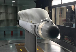
Figure 1 Jamming pod. Source: L3Harris Corporation.

Figure 2 Northrop Grumman’s AN/SPQ-9B radar. Source: Northrop Grumman Corporation.
According to Northrop Grumman, their AN/SPQ-9B can detect all known and projected sea-skimming missiles. In this application, the microwave SSPAs are packaged in aluminum boxes with SMA connectors.
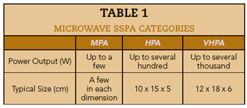
Several parameters characterize an SSPA, but the RF output power is almost always the primary consideration. This output power can range from a few watts (30 to 40 dBm) to several kilowatts. The RF power output can be continuous wave (CW) for EW or pulsed with a typical 10:1 duty cycle for radar systems. In this article, SSPAs are characterized as medium-power amplifiers (MPAs), high-power amplifiers (HPAs) and very high-power amplifiers (VHPAs). Table 1 shows a categorization of these classifications.
These amplifier designations can generally be described with the following characteristics:
MPAs (CW): Most often, GaAs-based MMICs in QFN packages with DC supply voltages typically around 12 V.
HPAs (CW): GaN-based MMICs for tens to hundreds of watts. Hybrid circuits are used for the higher power levels and LDMOS is used at lower frequencies. The DC supply voltage is typically 40 V. Multiple transistors or pallets are often used and the balanced circuit configuration is frequently adopted.1 The minimum requirement is two transistors or MMICs, per balanced circuit. This means there may be 20 transistors or MMICs used for 10 parallel circuits in a pallet.
VHPAs: Circuits use LDMOS or GaN discrete transistors. They are pulsed for radar applications with several kW peak power not uncommon. DC supply voltages are typically around 100 V or more. Multiple blocks, in parallel, are often used and the balanced circuit configuration is often adopted, like HPAs.
GaN HEMT devices, typically using GaN-on-SiC technology, are already significant and growing in importance in this industry. MMICs are used wherever possible, but discrete transistors within a hybrid circuit may be the best solution for higher microwave power levels. CW systems are required for most EW system applications, whereas pulsed amplifiers are common for most non-AESA radar systems. These systems generally operate in L-Band (0.3 to 2 GHz), S-Band (2 to 4 GHz), C-Band (4 to 8 GHz), X-Band (8 to 12 GHz), Ku-Band (12.4 to 18 GHz) and Ka-Band (26.5 to 40 GHz). In some instances, ITU band designations of UHF (0.3 to 3 GHz) and SHF (3 to 30 GHz) may be used.2,3
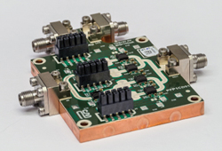
Figure 3 CMX90A705A6 Ka-Band MMIC-based SSPA. Source: CML Micro Compound Semiconductor Design team.
As a practical example, Figure 3 shows a MMIC-based Ka-Band SSPA developed by CML Micro Compound Semiconductor Design team. This SSPA uses six GaN-based MMICs designed by PRFI. Two of the MMICs are close to the input side with the remaining four located near the output. The device operates with a 10 percent duty cycle and provides an average output power of 5.5 W from 27.5 to 31 GHz.