
Electronic devices require a reliable source of electricity for stable operations, which is not always simple to deliver due to the potential for devices to be impacted by electromagnetic interference (EMI). EMI is an electromagnetic wave that induces an unwanted signal in an electrical system that can affect operational requirements. EMI can be caused by other electronic devices or it may occur naturally in the environment from lightning and other weather events like solar flares or static electricity. Figure 1 shows four different modes of EMI propagation:
- Interference can enter equipment directly through the cabling. This is conducted interference.
- Radiated interference can travel directly from the source to the affected equipment.
- Interference can exit an EMI source via a cable and subsequently be radiated from the cable to the affected equipment. The cable is a radiating antenna in this instance.
- Interference can radiate from an EMI source and be picked up by a cable entering the affected equipment. The cable is a receiving antenna in this instance.
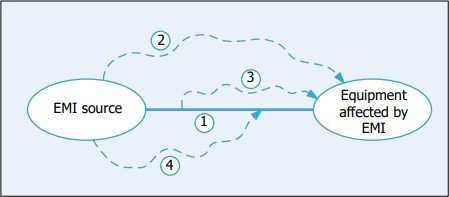
Figure 1 Four different modes of EMI propagation.
Depending on the severity, EMI can degrade a device’s performance, lead to a malfunction or cause the device to fail, which can be quite problematic for mission-critical electronic devices such as those used in military and aerospace equipment. For example, if someone is using their phone on a plane when they should not be, you cannot take a risk that this will impact airplane controls. You need EMI filtering to ensure it will never be a problem.
However, too often EMI filtering is an afterthought for electronic device designers and they end up needing to retrofit their devices to properly address the issue. Reducing or eliminating EMI is not only crucial to prevent devices from functioning improperly or failing but there are also regulatory requirements put into place by the FCC Part 15 and EU Directive 2014/30/EU that aim to reduce or eliminate EMI for many critical devices. Since EMI filtering is extremely important for many devices, yet seems complex, this article focuses on explaining the details of different methods for protecting electronic devices from EMI.
THE FARADAY CAGE
The ideal way to protect a piece of equipment or circuit from EMI is to completely enclose it in a metal or conductive box. This screened enclosure is called a Faraday cage. Radiated interference is prevented from adversely affecting the circuit because the Faraday cage creates an equal, but opposite, electric field inside the cage. This field cancels out the external electrical field and prevents the electromagnetic energy field from affecting the circuit inside the cage. This is shown, conceptually, in Figure 2.
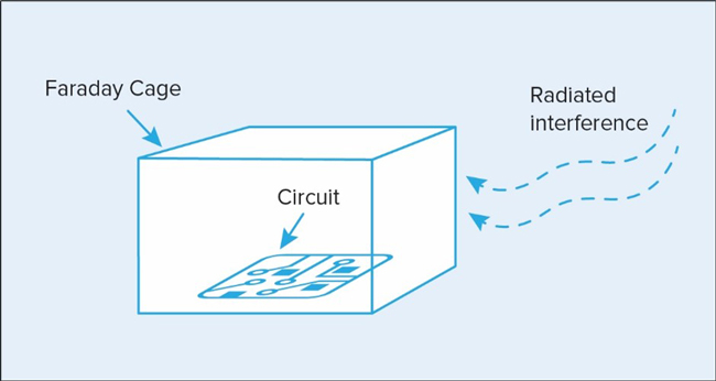
Figure 2 A representation of a Faraday cage protecting a circuit from radiated interference.
Most equipment requires input and/or output connections such as power cables or signal and control lines. These lines can act as antennae and pick up or radiate interference or introduce electrical noise and radiate it internally onto other wires and circuits. This means a Faraday cage, alone, likely will not be sufficient and some form of low-pass filtering will often be required.
PANEL MOUNT FILTERS
When used in conjunction with a Faraday cage, EMI filters can provide an ideal solution for removing EMI. Rather than blocking EMI like a Faraday cage is designed to do, EMI filters remove or filter out unwanted signal noise. Two types of EMI filters will be examined in this article: panel mount and surface mount.
A panel mount EMI filter is designed so that any incoming or outgoing cables pass through the filters. The desired signal is allowed to pass through the cable into the Faraday cage, unaffected. The higher frequency interference is removed by being passed through a capacitor to the ground, which is the body of the filter and into the wall of the Faraday cage in this case. Essentially, the EMI filter feeds the unwanted signal through the panel while protecting the circuit. This removes conducted interference and this technique is conceptually shown in the illustration of Figure 3.
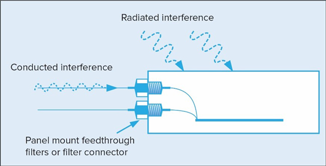
Figure 3 Panel mount filter removing conducted interference in conjunction with the Faraday cage.
There are several different electrical configurations available for feedthrough filters:
- C Filter: A feedthrough capacitor with low self-inductance that shunts high frequency noise to ground and is suitable for use with a high-impedance source and load.
- L-C or C-L Filter: A feedthrough filter with an inductive element combined with a capacitor. It is commonly used in a circuit with a low-impedance source and a high-impedance load or vice versa. The inductive element should face the low-impedance source.
- Pi Filter: A feedthrough filter with two capacitors and an inductive element between them. Ideally, this type of filter is used where both the source and load impedances are high.
- T Filter: A feedthrough filter with two series inductive elements separated by one feedthrough capacitor that is suitable for use where both the source and load impedances are low. Figure 4 shows the schematic configurations for these different filter types.
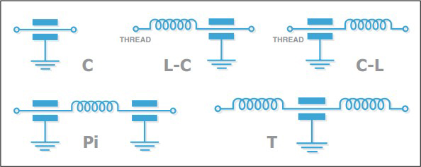
Figure 4 The electrical configurations for different types of feedthrough EMI filters.
APPLICATION CONSIDERATIONS FOR PANEL MOUNT EMI FILTERS
When considering the appropriate filter design, several other variables beyond selecting the appropriate electrical configuration for a panel mount EMI filter must be evaluated. These include the materials, capacitor construction and mounting techniques. The next section explores these factors in more detail.
Dielectric Material
Different dielectrics offer varying performance. This is because dielectric constant stability and therefore, the filter capacitance, can fluctuate with changes in operational and environmental characteristics such as temperature, applied voltage or age. This is important because reducing capacitance also causes the insertion loss performance to degrade.