
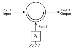
Figure 1 Three-port circulator with Port 2 terminated in ZL.
A receiver requires a narrowband front-end to reject unwanted signals at frequencies in proximity to the operating frequency. Conventional filters have bandwidths greater than five percent. Superconducting filters have been used to obtain much smaller bandwidths but require cryogenic cooling. The Grayzel Negative Resistance Amplifier (GNRA) has demonstrated a 0.5 percent bandwidth and analysis has shown that a bandwidth of 0.11 percent can be achieved.1 Analysis and experimental results are presented.
When a signal with power Pin is delivered to Port 1of a circulator with characteristic impedance Z0 and Port 2 of the circulator is terminated in an impedance ZL, the output power Pout at Port 3 is equal to Pin |ρ|2, where ρ, the reflection coefficient, is given by Equation 1.
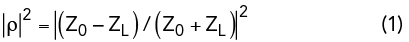
Figure 1 shows a three-port circulator terminated in ZL. If ZL is a resistance of Z0, ρ is equal to zero and Pout is equal to zero. If ZL is a reactance, |ρ|2 is equal to 1.0 and Pout is equal to Pin. If ZL is a negative resistance, then |ρ|2 given by Equation 2 is greater than 1.0 and the input power Pin is amplified. If, for example, R = -44.68 and Z0 equals 50 Ω, then |ρ|2 = 316.7 and Pout/Pin = 25 dB.
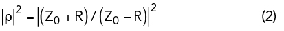
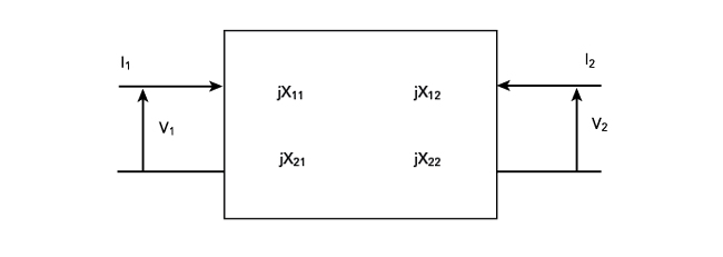
Figure 2 Lossless two-port network characterized by its impedance matrix.
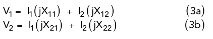
Figure 2 shows a lossless two-port network characterized by jX11, jX12, jX21 and jX22 defined by Equations 3a and 3b.
For a reciprocal network X21 = X12. If the network of Figure 2 is terminated in a positive resistance Rout, then V2 = - (I2 ) Rout. By solving Equations 3a and 3b one finds that the input impedance Zin+ is given by Equation 4.
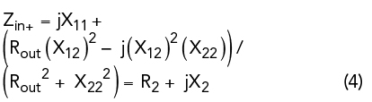
where, R2 and X2 are the real and imaginary parts of the input impedance Zin+. If the network of Figure 2 is terminated in - Rout, then the input impedance Zin- is given by Equation 5.
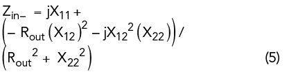
It can be seen from Equations 4 and 5 that Zin- = - R2 + jX2 .
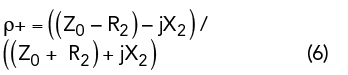
By substituting Equation 4 into Equation 2, the reflection coefficient ρ+, when the network of Figure 2 is terminated in Rout, is given by Equation 6.
By substituting Equation 5 into Equation 2, the reflection coefficient ρ-, when the network of Figure 2 is terminated in - Rout, is given in Equation 7. Then (ρ-)* is given by Equation 8, where (ρ-)* is the complex conjugate of ρ-, and |ρ-|2 is given in Equation 9.
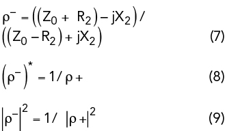
Figure 3 shows a GNRA containing a two-section filter resonant at 79.2 MHz with a bandwidth of 6.7 MHz when terminated in 50 Ω. When the filter is terminated in a negative resistance of 44.68 Ω, Equation 1 yields |ρ-|2 equal to 316.7 (25 dB) at frequency f0.
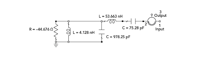
Figure 3 GNRA with a wo-section filter resonant at 79.2 MHz.
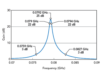
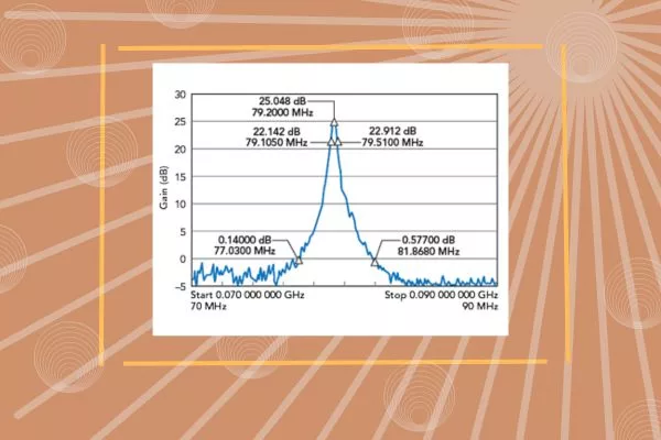
Figure 4 Results of an analysis of the GNRA in Figure 3.
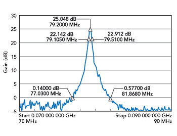
Figure 5 GNRA measured results.
If the filter has an attenuation of 3 dB at f1 and f2 when terminated in a positive resistance, then when terminated in a negative resistance of 44.68 Ω, |ρ-|2 equals 3 dB at f1 and f2 and the gain of the amplifier is then 3 dB at these frequencies. The gain of the GNRA at f1 and f2 is therefore 22 dB below the gain at 79.2 MHz.
If, for example, the two-section filter shown in Figure 3 had a 10 percent bandwidth, then the gain of the amplifier would be 22 dB below the gain at f0 at frequencies 0.95f0 and 1.05f0 where f0 equals 79.2 MHz. This result is independent of the number of filter sections; one or two sections will suffice.
COMPUTER ANALYSIS
Results of a computer analysis of the GNRA in Figure 3 are shown in Figure 4. The gain of the amplifier at 79.2 MHz is 25 dB and the bandwidth at a gain of 22 dB is 0.4 MHz (0.5 percent). The gain is 3 dB at 75.9 and 82.7 MHz, 22 dB below the gain at 79.2 MHz.
EXPERIMENTAL RESULTS
The GNRA in Figure 3 exhibits a negative resistance using an operational amplifier with appropriate feedback. The measured results in Figure 5 show a 3 dB bandwidth of approximately 400 KHz (0.5 percent). Gain is approximately zero at 77.0 and 81.9 MHz.
SUMMARY
Analysis of a lossless two-port terminated in a negative resistance has been presented which shows that the reflection coefficient of the two-port when terminated in a negative resistance is the reciprocal of the complex conjugate of the reflection coefficient when terminated in a positive resistance. The GNRA uses this property to realize very narrow bandwidth amplifiers. A bandwidth of 0.5 percent is experimentally achieved.
ACKNOWLEDGMENT
The author wishes to acknowledge the support provided by Dr. Ashok Gorwara and the staff of Gorwara & Associates International, Inc., 2200 South Ocean Lane, Suite 2002, Fort Lauderdale, Fla.
REFERENCES
- “Very Narrowband and Wideband Negative Resistance Amplifier with a Tunable Center Frequency,” U.S. Patent Application No: 17/873.838, to be published.
Editor’s Note: Although this work was accomplished at VHF frequencies, the method should apply generally to higher frequencies as well.