
.webp?t=1681996829)
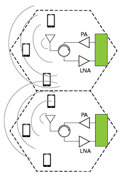
Figure 1 Traditional microcell base station architecture.
The superior performance of active/advanced antenna systems (AAS) compared to traditional passive antenna systems (PAS) is driving a transition towards AAS for base stations used in telecommunications applications. These AAS are composed of several to even hundreds of antenna elements that, depending on the design, require distinct RF signal chains to the antenna elements. This approach allows for MIMO and beamforming capability, but it also dramatically increases the antenna system complexity, though generally at lower RF power per signal chain. This changes the telecommunications RF front-end (RFFE) dynamic from a small number of very high-powered signal chain components to a multitude of lower-power components with different design criteria and considerations. The latest generation of RF silicon-on-insulator (SOI) component technology is well-suited to fill this new niche for telecommunications signal chain components for both sub-6 GHz and massive MIMO (mMIMO) transceivers.
TRANSITION TOWARD AAS
Traditional cellular mobile base stations are based on a homogenous cellular design with large base stations spaced sparsely to cover targeted regions. Covering these distances has traditionally required base stations to be located on large towers or the tops of tall buildings in more cluttered urban environments. Generally, the radio unit (RU) is in a location that is readily accessible to technicians with the antenna placed on top of the tower or edge of the building using a remote radio head (RRH) system. The RU routes antenna signals along lossy RF coaxial cables in a PAS.
This cellular model requires omnidirectional or directional antennas that radiate over a wide coverage area to serve as many users as possible. The amount of energy received by the user equipment (UE) is low when compared to the total radiated energy, resulting in low radiated energy efficiency. With only a single large transmitting antenna, the same signal must be sent to the entire coverage area. This scheme supports a limited number of simultaneous users from a given base station and is shown in the block diagram of Figure 1.
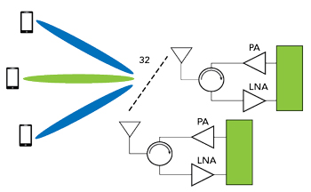
Figure 2 Front-end of 32-element mMIMO AAS base station.
This approach successfully served legacy devices and traditional use cases, but the number of mobile devices is growing. Growing numbers of devices and requirements for enhanced cellular performance are all factors driving the development of base stations using mMIMO antennas. These base stations are capable of supporting a significant number of UEs, but they necessitate a shift in architecture. As a result, there are significant ongoing development efforts aimed at MIMO and beamforming technologies to realize AAS.
The RF unit in an mMIMO AAS is located close to or integrated with the antenna. This makes the RF signal routing between the RU and antennas much shorter. The mMIMO arrays route transmit and receive signals to a large number of radiating elements. These antennas have at least one RFFE per group of antenna elements and may have one RFFE per antenna element. This architecture supports mMIMO access and beamforming, resulting in an antenna system with a controllable beam pattern that is compatible with spatial multiplexing. Spatial multiplexing allows for multiple simultaneous data streams between the base station and the UE to maximize capacity and coverage. The front-end of an mMIMO AAS is shown conceptually in Figure 2.
These mMIMO AAS are much more compact than traditional base stations, with a multitude of lower-power RF signal lines replacing a single large and less efficient signal path. The MIMO capability enhances radiated efficiency because beamforming architectures and mMIMO techniques enable more directional antenna patterns, concentrating the radiated energy from the base station toward the UE. Figure 3 lists some of the features, advantages and use cases for different base station classifications.
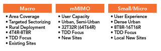
Figure 3 Base station differentiators.
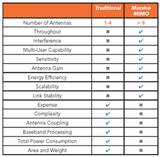
Figure 4 Comparison of traditional and mMIMO antennas. Source: Yole Developpement, “5G’s Impact on RF Front-End for Telecom Infrastructure 2021.”
Depending on the use case, MIMO and beamforming AAS can enhance the downlink and uplink signal strength and cell throughput by allocating multiple beams to one or more users. The highly directional beamforming antennas reduce transmitted and received interference. This can dramatically improve network performance within a cell and with adjacent cells, especially in interference-limited cell deployments. Figure 4 compares the features and performance of traditional passive and mMIMO base station antennas.