
In electrical components and circuits, noise effects with different physical causes occur everywhere. In crystal oscillators there are three primary noise generating mechanisms: A ubiquitous background noise due to the thermal motion of the atoms and molecules of all components creates an insurmountable noise floor, which mainly affects noise far from the carrier (white noise). Noise caused by semiconductor components is called shot noise which has a 1/f dependence on the frequency. The dominant noise source close to the carrier is called flicker noise, which largely depends on the quality of the crystal. A high Q-factor of the crystal suppresses noise near the carrier. Depending on the application, noise is described differently; phase noise, jitter and short-term stability are different ways of looking at the same physical phenomena. This article provides an overview of the interrelationships.
Ideal oscillators produce a time-dependent, sinusoidal output voltage of the form:
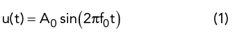
with amplitude A0 and frequency f0. This sine wave has a perfect period, and the Fourier transform of u(t) is a spectrally pure delta function δ(f-f0). A non-ideal, noisy signal u’(t) can be described in general terms by introducing a term for the amplitude noise ∈(t) and a term for the phase noise Δφ (t) of the signal in the time domain given by:
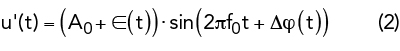
Here A0 is the amplitude of the pure sinusoidal signal and f0 its nominal fundamental frequency, which can be interpreted as a statistical mean value. In this case, the frequency spectrum is no longer spectrally pure, but a function of frequency, or more precisely, the Fourier transform of the time-dependent voltage signal.
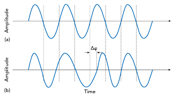
Figure 1 Pure sinusoidal waveform (a) and effect of a random, time-dependent phase deviation = δφ.
Figure 1 shows the short-term frequency instabilities caused by the phase noise term. They show up in the time domain as a deviation of the zero crossings (phase angle) of the actual signal waveform compared to the ideal sinusoid. A modulation of the amplitude is not shown in this figure.
In the following discussion, only the temporal change of the phase angle is considered, which is caused by random, and thus Gaussian distributed processes. In the following, the three most important forms of description, namely phase noise L(f), jitter ΔT(Δf) and short-time stability  are described.
PHASE NOISE
Considering the phase instability of a signal source as phase noise is one of the possible representations to be considered in this article. The amplitude of the phase noise signal L(f), more precisely the noise power spectral density of the phase noise, increases with increasing proximity to the carrier. An empirical description of the single-sideband phase noise is given by the so-called Leeson formula. It describes the amplitude of the phase noise as a function of carrier frequency f0 of the oscillator, its quality factor Ql, cutoff frequency fc, noise factor of the amplifier F, Boltzmann constant kB, absolute temperature T and output power Ps:
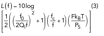
Without having to analyze this equation in detail, it is easy to estimate the behavior of phase noise for small and large frequencies f. For small frequency distances from the carrier, the two factors
 and
and  grow. Due to the monotonic property of the logarithm, L(f) also grows. Far away from the carrier, for f → ∞, these two terms vanish and the phase noise tends toward the value
  .1
.1
Therefore, it is very important that a requirement for maximum phase noise includes the exact distance from the carrier at which a specific value of the phase noise is specified. The fraction close to the carrier is largely determined by the Q of the crystal, where the phase noise fraction for frequencies above 1 kHz is determined by the noise of the semiconductor devices used.
In principle, the phase noise of an oscillator can always be measured (approximately) directly by means of a spectrum analyzer if the local oscillator of the measuring device has a significantly better phase noise performance than the device under test (DUT) and the sampling rate is far above the Nyquist frequency of the signal. Spectral analysis using a fast Fourier transform (FFT) can be used to determine the spectral distribution of the noise far away from the carrier frequency. Here, however, the measurement is limited by the noise characteristics and the limited sampling rate of the spectrum analyzer.
In the following, a much more precise measurement method is presented, which also enables the measurement of DUTs with extremely low phase noise. This method is generally valid and suitable for oscillators with high phase noise as well. To determine phase noise, the so-called phase detector method with phase locked loop (PLL) synchronization of the reference phase is used.
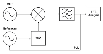
Figure 2 PLL measurement for determining the phase noise of an oscillator (DUT).
As shown in Figure 2, this method uses a quadrature mixer as a phase detector. Here, the reference oscillator and the mixer form a PLL. By manipulating the control voltage of the reference oscillator, a condition is sought in which the signal of the test oscillator (DUT) and the signal of the reference oscillator have a phase shift of  with respect to each other at the same frequency. Both signals are mixed in a mixer element. In general, for given input signals fa and fb, the output signal of a mixer can be described as a superposition of the high frequency sum signal (fa+fb) and the low frequency difference signal |fa- fb|.