
5G communications have supported the deployment of mmWave antenna array beam steering technologies at an unprecedented commercial scale. As per 3GPP1 and CTIA2 test specifications, 5G mmWave capable mobile phones must undergo a large number of tests to guarantee adequate performance. The defined measurement methodology relies on far-field over-the-air (OTA) assessments in compact antenna test ranges (CATR). As temperature influences the active electronics in the wireless devices and, hence, the beamforming characteristics, OTA measurements are also required in temperature conditions ranging from -10°C to +55°C, per 3GPP test specifications. For such tests, an innovative realization of a CATR with an embedded thermal compartment meeting conformance and compliance testing needs is required.
3GPP requirements for RF conformance testing of mobile devices or user equipment (UE) are essentially designed to avoid problems that would impair the functioning and performance of wireless networks. Up until 4G and 5G FR1 (i.e., frequencies below 7.125 GHz), all 3GPP conformance evaluations were based on conducted measurements, typically achieved by connecting RF cables at the antenna ports of the device under test (DUT). A major change occurred in 5G, with the added FR2 frequency range in the mmWave spectrum (i.e., FR2-1: 24.25 to 52.6 GHz and FR2-2: 52.6 to 71 GHz). As UE FR2 antennas are dynamic beam steering arrays, the conducted approach became irrelevant because the overall performance of a DUT is intrinsically linked to the antenna. In addition, the high level of integration of arrays and RF front-ends enabling the operation of such technologies makes it practically impossible to reliably connect cables at adequate points.
OTA assessment appeared as the correct and most straightforward approach for testing, and far-field (FF) spherical measurements in anechoic chambers became the basis for all sorts of tests of FR2 UE. Because the UE can be large (e.g., a mobile phone, tablet or laptop) and manufacturers are not constrained to communicate the exact location of the antenna elements, the so called black-box approach was adopted, with the whole DUT placed within the quiet zone (QZ) of the FF measurement setup. The CATR was adopted by 3GPP as the reference test environment because of its capability to provide a large QZ within a confined space.
Since UEs are used in diverse environmental conditions, and temperature will influence the active electronics in the DUT and affect the beamforming performance,3 spherical OTA measurements at extreme temperature conditions (ETC) ranging from -10°C to +55°C became part of the 3GPP UE RF conformance test specifications.
ETC REQUIREMENTS
Designing a CATR that enables dual-axis rotation of the DUT, to perform accurate FF 3D measurements under ETC, sounds simple but is a complex engineering problem. The complexity increases when considering the need for fast testing—hence fast temperature ramps—while protecting the anechoic chamber and positioning system from damage due to the high or low temperatures and maintaining the shielding effectiveness of the chamber. Combining the requirements from 3GPP and typical customer needs yields the following constraints on the design of the CATR environment for ETC testing:
- Positioning system azimuth range from 0 to 360 degrees and an elevation range from 0 to 120 degrees, not reduced by the air pipes or other ETC requirements on the positioner
- Spherical measurements with the device temperature from -10°C to +55°C (as defined by 3GPP) and an extended temperature range of -40°C to +85°C (for customer stress tests)
- Minimum DUT dimension of 40 cm diameter with the ETC solution in place
- 30 cm diameter QZ during ETC testing, with an uncertainty better than 0.9 dB
- Chamber shielding > 70 dB, not degraded by air injection pipes
- Time for DUT heating and cooling as brief as possible.
Innovation was necessary to design a system complying with this set of criteria, leading to many sophisticated details to solve the challenges, resulting in several patents for multiple components of the final ETC OTA solution.4
Exposure to a temperature range from -40°C to +85°C can damage the absorbers in an anechoic chamber, as well as the motors and drives in a 3D positioner. To protect from this, the DUT is enclosed in a thermal compartment within the OTA chamber, which contains the cold or hot air as hermetically as possible. The rest of the chamber is ventilated to maintain close to the ambient temperature. One upside from limiting the volume exposed to the temperature swings is reduced energy and air volume that must be provided to stabilize the DUT at the ETC condition. This also reduces the time necessary to reach the target temperature.
While this approach offers the benefits noted, it is not without major difficulties. First, the thermal enclosure must be sufficiently RF transparent to minimize any impact on QZ uniformity and DUT radiation. Yet the enclosure must be stable and withstand the increase in inner air pressure from the temperature air flow while isolating the hot and cold air flow from the surrounding environment. All mechanical parts of the thermal enclosure, as well as the air pipes which connect to it, must support full 3D movement of the dual-axis positioner—hence the DUT—while being airtight. The air hoses must run in and out of the chamber through RF shielded walls without compromising the shielding effectiveness.
CHAMBER DESIGN
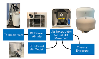
Figure 1 Air flow of the ETC test system.
All these considerations led to a system concept with the air flow chain shown in Figure 1. Compressed dry air at the desired temperature is provided by an external climate machine called a Thermostream. Connected to power and the central compressed air supply, it provides the required air volume between the minimum and maximum air temperatures to the air inlet of the anechoic chamber. Running the air pipes through the shielded chamber walls requires RF filtered air feedthroughs, which comprise multiple metal pouches filled with absorber, guiding the air through winding pipes to the inside of the chamber.