
The pandemic marked a turning point for the broadband industry, leaving network providers struggling to meet rising consumer demand. While the digital divide is not a new phenomenon, its negative impact on both individuals and society increased because of COVID-19. Governments and operators across the world are responding, working to deploy robust infrastructure that delivers super-fast broadband connectivity, but we are still a long way from achieving this goal, with 50 percent of the world’s population without reliable connectivity.
Existing network technologies like twisted pair and coax cannot provide the required capacity, while fiber to the home (FTTH) deployments are often unfeasible because they are prohibitively expensive and slow to deploy. Fixed wireless access (FWA) technology, on the other hand, is an attractive solution to the challenge of delivering connectivity to rural and other underserved areas. FWA can fill the Gbps broadband need where fiber is not commercially or logistically viable, bringing Gbps speeds to the home with a total cost of ownership less than half of FTTH.1
While the mid-band spectrum below 6 GHz provides range, the mmWave bands provide capacity. 5G FWA uses the 30 to 300 GHz frequency range, corresponding to wavelengths spanning 1 to 10 mm. mmWave technology is an essential component of 3GPP’s 5G standards, as it enables the multi-Gbps data rates promised by 5G. While most mmWave usage is centered on the licensed spectrum bands used by the tier 1 operators, the unlicensed band in the 60 GHz range is currently underused and can extend broadband networks to rural and other underserved areas.
60 GHz provides high speed and low latency internet connectivity, making it an attractive and efficient choice for last mile access. 60 GHz FWA enables employees and businesses to remain productive via a high performance and reliable network and can help connect a world of people via the “metaverse” and other extended reality technologies that require high speed, low latency internet access. The opportunity for 60 GHz is large, and the FWA industry is in the process of realizing its potential.
60 GHz CMOS
Pharrowtech, an imec-backed fabless semiconductor and antenna provider, designs and develops hardware and software for next-generation wireless applications. Responding to the 60 GHz FWA opportunity, Pharrowtech is commercializing a fully integrated CMOS beamforming transceiver and phased array antenna. Based on 15 years of R&D at imec, Pharrowtech’s founder, Wim Van Thillo, saw a lack of cost-effective options for the mmWave phased arrays required by FWA systems. Based on the belief that CMOS is the most cost-effective semiconductor technology for FWA, Pharrowtech was launched to commercialize a CMOS-based transceiver. Based on its R&D and prototypes, the company has raised €21 million to scale the RFICs into production.
The core intellectual property developed at imec was a transceiver for the unlicensed 57 to 71 GHz band designed in mature 28 and 40 nm CMOS process nodes. The transceiver architecture is based on the 802.11ay standard. Compared to 5G New Radio, the 802.11ay architecture yields a lower complexity modem and software design, resulting in lower system cost. (Based on its commercial potential and the need for more spectrum, the 60 GHz band has been added to 3GPP Release 17.)
The first product released by Pharrowtech, the PTR1060, is a packaged transceiver with 32-way beamformer and transmit (Tx)/receive (Rx) switching, fabricated in CMOS (see Figure 1). The RFIC covers 57 to 71 GHz and supports channel bandwidths to 4.32 GHz. The transceiver uses a direct conversion architecture to minimize the circuitry and reduce calibration complexity. A universal I/Q analog I/O was chosen to interface with commercially available baseband ICs for digital signal processing.
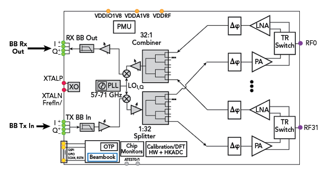
Figure 1 PTR1060 IC block diagram.
High-resolution phase shifters in the beamformer provide 1 degree phase resolution, which is useful for large arrays. Supporting 1024 beam book entries, a full 90 × 90-degree antenna field of view (FoV), defined as ± 3 dB per direction, can be covered with less than 3-degree beam steering resolution. The PTR1060 integrates a powerful, flexible high speed digital control block supporting both standard (Q-)SPI and a proprietary HSCL digital interface for fast beam steering, AGC and Tx/Rx switching. A wideband phase-locked loop (PLL) was designed together with the LO path in a way to provide immunity to power amplifier (PA) pulling. The digital I/O runs from a standard 1.8 V supply, while the main supply voltage of 0.9 V is provided by the on-chip power management unit (PMU) or, alternatively, a dedicated external supply. An on-board oscillator using a low-cost crystal provides a 40 or 45 MHz reference clock.
By choosing CMOS, a large, cost-effective SRAM has been integrated on the IC. It stores separate beam book entries for Tx and Rx, supports fast gain switching for transmit while ensuring 11ay timing-compliant AGC control, with 0.5 dB gain steps for the Rx chain. Programmable baseband filters are included in both the Rx and Tx paths, avoiding the need for external anti-aliasing filters in the Rx chain or reconstruction filters in the Tx chain. The sub-channel frequency tuning capability of the integrated frequency synthesizer provides sub-channelization options for dense 3GPP deployments in the unlicensed 60 GHz band.
Pharrowtech’s transceiver is encapsulated in a BGA package with a standard 500 µm ball pitch. The packaged IC can be integrated with an antenna (the PTM1060 antenna module) by mounting it on a substrate containing an 8 × 8 patch antenna. The RFIC is flip-chip mounted to the antenna substrate, with the backside of the die exposed for efficient thermal management. In a system, the antenna-RFIC module is mounted to a system printed circuit board (PCB) with an integral thermal heat sink for the RFIC (see Figure 2). To help users evaluate the RFIC in lab or field environments, Pharrowtech has developed an evaluation kit using this same approach, where the PTM1060 is mounted on a reference PCB.

Figure 2 Cross-section of PTM1060 and antenna substrate mounting on a PCB.
The 8 × 8 patch antenna array provides 20 dBi net gain and a beamwidth of 16 degrees, achieving a 90-degree azimuth × 60-degree elevation FoV with 6 dB combined azimuth/elevation scan loss at the edges, i.e., 3 dB per direction. The array uses two patches per antenna element and is fabricated on substrate material with less than 0.1 dB/mm loss. The array substrate uses the standard 800 µm ball pitch.
LINK PERFORMANCE
The performance of a 60 GHz link using the CMOS transceiver with a customized array antenna at each end has been simulated (see Figure 3). The figure shows the results of a Matlab estimate of link range versus choice of 802.11ay modulation and coding, defined as the MCS level. The simulation uses the RFIC and antenna module performance parameters to calculate the available Tx output power and Rx sensitivity, considering the signal properties at the selected MCS level and the effective beam power and sensitivity across the beam FoV. The simulation combines both beam cases and the effects of rain (assuming rain zone K) on path loss. For each modulation depth, the PA back-off is increased from the 1 dB compression point to generate the curves shown in the plot. For a 1 Gbps data rate (MCS 3), a range of greater than 150 m is expected during rainy conditions in rain zone K; it increases to more than 300 m for the ideal channel conditions at boresight. At MCS 12, a data rate greater than 3 Gbps can reach a range greater than 100 m at boresight.
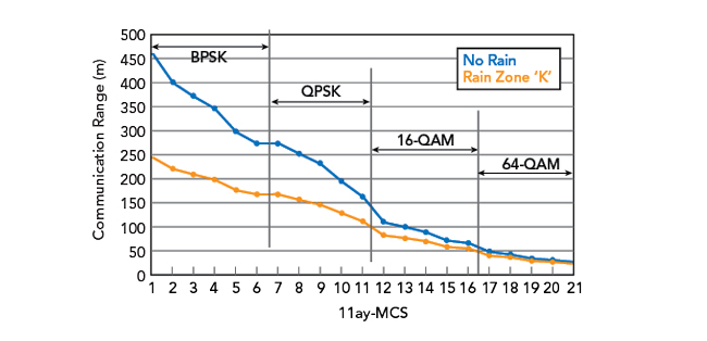
Figure 3 Predicted link performance.
CMOS vs. SiGe BiCMOS
Pharrowtech’s RFIC is on par with the best performing SiGe BiCMOS transceiver RFICs, providing approximately 40 dBm EIRP, yet with a smaller antenna substrate or half the DC power consumption compared to the existing SiGe products: typically, 5 W DC power consumption in Tx mode. With a 60 GHz carrier, it has phase noise of -99 dBc at 1 MHz offset. The Pharrowtech RFIC has 32 active paths, double the number available from commercial SiGe BiCMOS products, and a beam table size of 1024 × 2 entries for Tx and Rx, larger than any other RFIC currently available. Comparing the die areas of the RFICs on the market, the CMOS transceiver is smallest. CMOS’ main supply voltage of 0.9 V, 1.8 V for I/O is lower than the supply required by SiGe RFICs: 1.65 to 3.3 V for the main PA supply.
The design of such a complex mmWave beamforming transceiver requires a rigorous design and verification methodology. First, all system functions must be included in the design to ensure straightforward system development: the signal path, local oscillator subsystems, crystal oscillator and system reference clock generation, start-up circuits such as power-on-reset and digital clock enable, power management, generic and custom digital control interfaces, calibration and self-test provisions. To ensure faultless operation of the integrated system, each block must be finalized with high confidence in the silicon’s performance before the final layout is delivered to the foundry for manufacturing.
The intrinsic difficulty of working at 60 GHz requires more elaborate 3D electromagnetic (EM) modeling and co-simulation than used with sub-6 GHz designs. In pre-tape-out design and verification, the mmWave models include all the coupling effects of the package, antenna substrate and PCB. To avoid lengthy and costly design and layout iterations, these effects must be considered from the start of the design; they cannot be left to a verification check at the end.
Pharrowtech has a team with multiple decades of experience designing products verified to the high standards necessary for both performance and reliability. By following this structured design and verification methodology and elaborate EM modeling using leading simulation tools, the team yielded a fully functional PTR1060 prototype on the first pass, and the first samples met customer expectations.
SUMMARY
Clearly, connectivity is pivotal to maintain societal and commercial cohesiveness in a post pandemic world. The global demand for broadband internet will only increase, so operators must adopt technologies to meet this need. FWA can provide broadband service with less construction and for a much lower cost than fiber. However, certain implementation challenges must be addressed. A CMOS integration will help reduce implementation costs and system complexity while a tested antenna array module will lower a customer’s technical expertise needed to add mmWave connectivity. No doubt mmWave CMOS will increase the capabilities of FWA, helping to meet the demands of a new generation of high data rate wireless networks.
Reference
- 1.S. Weston, “5G FWA could ‘Halve the Cost’ of Rural Full-fibre Rollout,” ITPro, July 2021, Web: www.itpro.co.uk/mobile/5g/360354/5g-fwa-could-halve-the-cost-of-rural-full-fibre-rollout-says-three.