
At a basic level, the Q of the resonator and the order of the filter are the most important factors determining the center frequency insertion loss and rejection slope. However, a typical filter spec is defined by insertion loss across the passband instead of at the center frequency and rejection at a particular frequency instead of a rejection slope. To meet a real filter specification requires the design pay careful attention to the insertion loss at the edge of the passband and the rejection close to the passband. Therefore, comparing different filter technologies requires comparison of not only the available Q and realizable filter order, but also the flexibility to implement different design techniques, including agreement with simulation.
Common filter technologies used today include acoustic wave filters, cavity filters, lumped element filters and planar filters. In traditional space constrained, “low frequency” environments such as handsets, Wi-Fi and many other consumer products, surface acoustic wave and bulk acoustic wave filters are extensively used. They offer superb rejection, low loss and small form factor but are limited to ~1 W power handling and frequencies below ~8 GHz for applications that drive significant volume. For lower volume applications with more available board space, a lumped element filter can offer low cost and good performance below 6 GHz but has poor performance at microwave frequencies.
On the other end of the spectrum, cavity filters provide the ultimate in rejection with very low loss and high power handling at microwave frequencies but are physically large, require hand tuning and are costly at any volume. These are used broadly in high-power communications systems such as macro base stations for cellular networks. Between these extremes in size and cost is the class of filter that Marki and our customers use most frequently: planar circuit filters. Planar circuit filters implemented in MMIC technology offer an excellent tradeoff between electrical performance, size, development time, development cost and unit cost for broadband microwave systems (see Table 1 for a comparison of five filter technologies). Marki is not tied to any fabrication technology, as we have the capability to design on laminate, thin film—ceramic, glass, sapphire and other exotic materials—or GaAs, what we call “MMIC filters.” While not traditionally considered for filter fabrication, MMIC offers the best combination of performance, cost and consistency.
A planar filter consists of a dielectric substrate with metal printed on top. The metal is patterned to electromagnetically couple resonators to yield a desired response. How this is done is the subject of countless textbooks and publications and is beyond the scope of this article. For an excellent overview of planar filter design, we recommend “Microstrip Filters for RF/Microwave Applications” by Jia-Sheng Hong. The art of planar filter design involves the careful choice of filter topology, resonator, circuit layout, optimization and tuning. A vast number of techniques are available to a filter designer; quickly narrowing the scope of options to compromise between size and performance is critical. While it takes only minutes to determine the best filter topology for a specification, it can often take several days of modeling and simulation to arrive at the final solution.
The design of a typical distributed planar filter is similar for the various fabrication methods (i.e., laminate, thin film including ceramic, glass, more exotics and MMIC) and largely requires the same software tools. Critical differences between the planar filter manufacturing methods include:
- Some fabrication processes support lumped and semi-lumped inductors and capacitors. The availability of these components impacts the variety of filter topologies that can be realized and strongly influences the achievable size.
- The dielectric and metal material properties and thicknesses vary among the processes. They are critical for determining the minimum size of a filter design and also dictate the available Q-factor and overall size of each resonator.
- The tolerances of the manufacturing processes can vary wildly. The tighter the tolerance, the better the filter repeatability from unit to unit and lot to lot. Tighter tolerance enables superior design flow for matching simulation and measurement—critical for first-pass design success.
MMIC FILTERS VS. LAMINATE
It is common practice to print filters in-situ on the circuit board that holds all the other components in an RF system. This do-it-yourself approach may seem practical and low-cost, but it introduces hidden costs and risks to system performance. These include:
Repeatability risk — While laminate filters are straightforward to design, the realistic manufacturing of laminate boards, especially multi-layer RF boards, is subject to routine variation in etching and lamination thickness. The typical etching tolerance of a laminate board is 25 µm, which translates to dimensional variation that will detune the filter. In some designs, errors of 2 to 3 percent in resonator frequency or coupling factor can be very problematic, and a poorly controlled laminate process can easily exceed 10 percent dimensional error in certain circumstances. A typical MMIC technology is two orders of magnitude more accurate with line and space accuracy measured in fractions of microns.
In-situ performance risk — The performance of a laminate filter is known to vary but, unlike a MMIC filter, it cannot be tested prior to assembly. A system must be completely assembled and found to fail a spec before the underperformance of the in-situ filter can be identified. This introduces significant cost and risk to a production design, as a completed board may be as expensive as 100 discrete filters.
Size risk — Due to the ∼4x higher dielectric of GaAs compared to the most common laminates and the fine tolerance of MMIC fabrication, a MMIC filter can be significantly smaller than an equivalent laminate filter. Any system revisions are easier to absorb with a small footprint.
Design flow risk — MMIC filters use a very well-vetted design flow, with first-pass success the standard expectation. The time to a successful design is understood and can be planned with confidence. A laminate design done in-house may or may not meet the schedule.
MMIC VS. THIN FILM
On the surface, a MMIC filter and a thin film filter appear similar: both are surface mountable with standard pick and place machines and reflow ovens. Both offer the ability to test and guarantee performance. Both are smaller than a laminate filter. The advantages of a MMIC filter over thin film are subtle and involve the manufacturing process used to create each type:
Size — While both are small, a MMIC filter can be 10× smaller than an equivalent thin film filter due to the high dielectric constant of GaAs, the small lines and spaces realized with MMIC lithography and the availability of extremely small, lumped element inductors and capacitors.
Substrate — GaAs has a Dk of 12.9, while alumina (the most common thin film material) has a Dk of 9.8. GaAs also has a superior dielectric loss tangent.
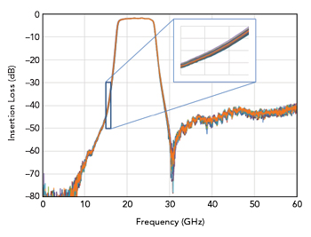
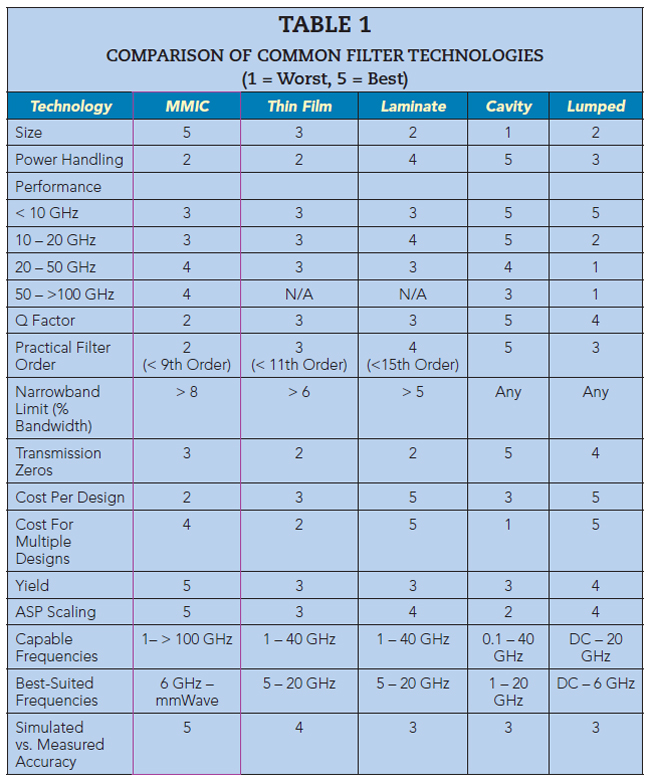
Figure 3 Sample of 24 typical MMIC filters from a lot of > 8000, showing fabrication repeatability.
Repeatability — The GaAs substrate material used to fabricate MMICs is a very tightly controlled single crystal produced in high volume. The dielectric constant and thickness are nearly identical from wafer to wafer. MMIC processing tolerances are exceptional—measured in fractions of a micron—owing to the decades of knowledge in the semiconductor manufacturing industry. Thin film circuit fabrication is a boutique technology understood by only a few domestic firms, and their manufacturing processes are not well controlled in comparison to ICs. To illustrate the repeatability of MMIC filters, Figure 3 shows the variation in the insertion loss of a sample of filters from a production lot of over 8000 filters.
Scalability — Closely related to repeatability is scalability. Wafers for GaAs can be larger than thin film—they are usually 6 in. for GaAs MMIC versus 2 in. for thin film—and they can be run in larger lots through the factory. For these reasons, MMIC filters can easily and quickly scale to millions of units. By contrast, the thin film industry has consolidated in recent years, partly forced by persistent capacity constraints. Thin film providers often struggle to meet volume needs.
Cost — For a single design, a MMIC is more expensive. For multiple designs—typically four or more—MMIC designs have cost parity with thin film and can even be lower cost. MMIC manufacturing is well suited for multi-project wafers, meaning many designs can be run on the same mask, and once a design is in production, the repeatability and scalability translate to a massive cost advantage. As a rule of thumb, cost savings can be achieved with MMIC filters once volumes exceed hundreds of pieces.
High Frequency Performance — The fine lines and gaps of MMIC lithography and the relatively thin substates support MMIC filters easily covering frequencies beyond 100 GHz. Thin film filters struggle in performance and consistency above 20 GHz.
Integration — A MMIC filter can be integrated directly with another MMIC function such as an amplifier or switch. It can easily be co-packaged into a standard surface-mount package or multi-chip module.
THE PROMISE OF MMIC FILTERS
Figure 4 shows the performance of four recent MMIC filters developed at Marki, demonstrating the agreement between the simulation and measurement. The simulations are the original design files, with no tuning to match experimental results. The four filters range from four to eight orders and employ different topologies. Owing to the novel capabilities of the MMIC process, some of these filters use lumped elements to enable topologies that cannot be fabricated as thin film or laminate circuits.
Figure 4 Comparison of simulated and measured responses for four filter designs, each 3.1 mm x 3.1 mm or smaller and fitting in a 5 x 5 QFN package.
Lumped and quasi-lumped topologies offer several benefits including filter miniaturization and re-entrant mode mitigation. For example, the MFB-7950 response shows the re-entrant mode is well beyond 3fo, a characteristic advantage of the loaded resonator technique. The fine geometric features available with the process enable precise tuning and optimization of features, such as transmission zeros via cross-coupling of resonators.
These results in Figure 4 show near-perfect match between simulation and measurement. This is the most important feature. By developing the design flow and optimization procedure over several years, Marki has shown that it is possible to quickly and accurately arrive at a design that will be reproduced by the foundry. First-pass design success means the development cycle is as short as possible: New designs can be turned in days, followed by fabrication and packaging lead times of 10 to 14 weeks, on average. This puts the MMIC development cycle in line with traditional manufacturers, albeit with significantly better first-pass confidence that “you measure what you simulate.”
Historically, semiconductor technology was not considered viable for a high mix of highly customized filters manufactured in low volume. It was widely assumed that the upfront costs of MMIC development negated the lower per-unit cost in production. We have discovered that a well-crafted MMIC design flow achieves first-pass success and the approach is cost-effective for custom filters, as long as the upfront costs are shared across multiple designs. Trends toward smaller form factor, higher volume, higher frequency filter requirements provide further incentive for custom MMIC filter solutions. MMIC filter technology offers a lower risk path to first-pass design success compared to incumbent technologies. Marki has demonstrated competitive filter performance at a fraction of the size of competing technologies, with improvements in performance and size ongoing. Enabled by advanced design and process improvements, the dream of best-in-class, rapidly designed, small form factor MMIC filters has become a reality.