
Radar was a system only possible to conceptualize at the end of the 19th century, after the Scottish mathematician and scientist James Clerk Maxwell described the classical theory of electromagnetic radiation and German physicist Heinrich Rudolf Hertz first used an antenna to prove the existence of the electromagnetic waves predicted by Maxwell’s equations. But the first real radar detection was in the early 20th century by Christian Hülsmeyer, a German physicist, with the equipment he called the Telemobiloscope. At the time, the equipment could detect the presence of a target but not its distance or speed.
The first radar system that was operational occurred a few decades later, and radar techniques progressed significantly during World War II, mostly for military applications. From there, radar continuously evolved to adjust to new threats and targets in diverse environments and to counter attempts to disable detection, such as jamming or to avoid detection, by more sophisticated targets.
The first modern radars used a rotating dish and high power amplifiers based on traveling wave tube technologies. They evolved with more sophisticated use of RF principles, such as Doppler effects, to estimate the range and speed of the target. German engineer and physicist Karl Ferdinand first showed phased array transmission in one direction in 1905. By World War II, American physicist Luis Alvarez had already developed rapidly steerable phased array radars; however, rotating dishes remained the main technology for several decades. In the 1980s, phased array systems were introduced, but not widely adopted due to size and little practicality, as they required data transfer to a computer to process the data and recreate the target. Phased array techniques only became practical with advances in electronics, largely highly integrated semiconductors that enabled the solid-state arrays developed at the end of the 20th century (see Figure 1).1
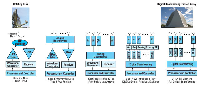
Figure 1 Evolution of radar, from the rotating dish to the active phased array with digital beamforming.
ERA OF THE PHASED ARRAY
Active electronically scanned array (AESA) radar has enabled significant improvements in radar capabilities since the late 1990s, and they continue to evolve to larger and more sophisticated arrays. AESA radars use a “phased array” antenna: an array of antenna elements or radiators, each provided with a signal having a different phase shift, which creates one or more beams. The beams result from the constructive or destructive interference of the waves from each element: in-phase signals superpose and amplify in a particular direction. Designed with enough elements appropriately spaced, the beam can have a high gain main lobe in one direction and low sidelobes. By switching antenna elements or changing the relative phases among the elements, the beam can be steered to concentrate the energy in a different direction.
Modern radars resist jamming by changing the frequency of each pulse or using a chirp technique, which spreads the frequency across a wide bandwidth during a single pulse. Elevation and azimuth beams with Doppler processing of the received signals is the basis of 3D radar, where the location of an object and its speed are determined with a more accurate identification of the object—differentiating a bird from a drone, for example.
The evolution of radar is driven by the need to detect and quickly respond to more sophisticated threats. New threats harder to detect are always emerging, such as smaller targets like drones or drone swarms, hypersonic weapons and stealth fighters. The evolution also reflects the need to support air traffic control, weather formation monitoring, collision avoidance and autonomous cars, a few of many new applications. The common themes for improved performance are greater range, finer resolution, lower detection threshold, precise spatial envelope control, multiple frequency band coverage and mission convergence. Achieving these requirements relies on disruptive architectures and advanced electronics.
BEAMFORMING
AESAs use three beamforming techniques to create and manage multiple antenna beams: analog, digital or hybrid. The best approach depends on the tradeoffs to accomplish the system’s mission. Today, the most popular architecture for advanced radar is a combination of analog and digital beamforming.2 These hybrid architectures employ distributed mixed-signal converter nodes feeding RF beamforming subarrays. The trend is toward more mixed-signal nodes feeding smaller RF subarrays, as RF sampling moves toward the individual elements.

Figure 2 Phased array using analog beamforming.
At higher frequencies and wider bandwidth, data throughput requires increased processing by the baseband processors, which increases power consumption. To mitigate this, the system can compromise converter performance by choosing lower bit resolution and power dissipation. However, this often yields undesirable signal quality, system performance and flexibility. So the tradeoff between digital processing bandwidth and acceptable cost and power will pace the adoption of wideband digital beamforming (DBF) at every element. However, large investments in semiconductor technology to improve data converter bandwidth and power efficiency will ultimately make wideband DBF at every element possible.
Radar performance improved dramatically with the transition from mechanical to AESA, and comparable improvements in performance will occur with the move from analog-to-digital beamforming as future systems become fully digital. With more converter channels located closer to the array elements, array gain improves the signal-to-noise ratio, although front-end adaptive RF signal conditioning is required to preserve the dynamic range in “blocker” environments. DBF enables flexibility: adjustments to a mission and supporting different missions, configured with system software. This multi-mission capability will enable system size and weight to be tailored for space-constrained systems, such as airborne.
Most current radar architectures in service today rely on analog beamforming (see Figure 2). The traditional analog approach uses analog phase shifters to make fine adjustments for beam steering, realized with circuits that are practical and relatively inexpensive. The analog signal chains from the antenna elements are combined and converted to digital for processing. With larger arrays, the elements are usually grouped into subarrays, with multiple analog-to-digital converters in the system. These subarrays currently provide the most practical implementation on the path to DBF: a hybrid architecture that significantly reduces the number of digital channels, associated data processing and power consumption.
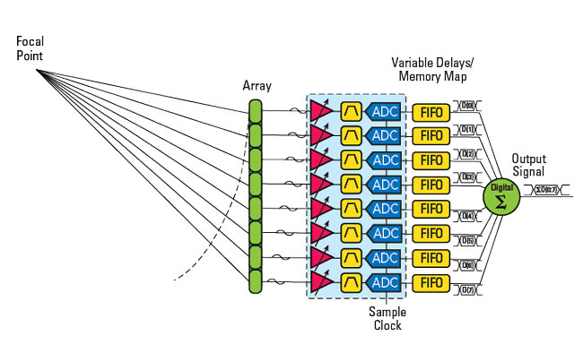
Figure 3 Phased array with digital beamforming.
As noted, the architecture offering the most flexibility and best performance, albeit with challenges, is full elemental DBF. With this architecture, a data converter processes the data from each element’s front-end module (see Figure 3), eliminating the analog beamforming layer. With DBF, many beams can be simultaneously formed and steered, the number limited only by digital signal processing (DSP) capacity. This architecture brings flexibility and arguably better reliability, with the attendant challenges from the amount of digital data to be processed, synchronizing multiple channels and minimizing the size, weight, power and cost (SWAP-C) of the array (see Table 1).3 Reviewing the benefits of DBF shown in the table:
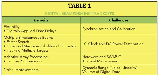
- Digitally applied time delay overcomes pointing errors caused by analog phase shifters. Applying phase and amplitude digitally overcomes many of the errors caused by analog circuits.
- Multiple simultaneous receive beams enables an area to be searched more quickly. The maximum likelihood estimation of detecting a specific target is improved with additional processing techniques applied to the beams.
- Adaptive array processing can suppress jamming by nulling interfering sources. Increasing the number of digital channels increases the number of interfering sources that can be eliminated, although practical implementation of this capability has not yet been realized.
- Noise and dynamic range can be improved by combining distributed receiver channels with multiple waveforms.
However, DBF poses significant challenges, particularly with practical implementation:
- Synchronization and calibration of the multiple waveform generators and receiver channels is challenging, including channel-to-channel drift and calibration when first powered on.
- Routing the local oscillator and DC power distribution throughout the array can be complicated and difficult to implement.
Hardware implementation and associated SWAP-C are increasingly challenging. The hardware cost, power consumption and thermal dissipation increase because signal processing is required at each element. The element spacing—a half wavelength or less to avoid grating lobes in the array—shrinks at higher frequencies, posing size constraints as each signal chain must fit within the area allotted to the element. The array thermal design must comprehend the added electronics at each element and the spacing constraints.
Assessing these tradeoffs, DBF can be a cost-efficient architecture for L- and S-Band systems when used to achieve the highest performance with multiple simultaneous beams and ensure flexibility. However, as the operating frequency increases into X-Band and beyond, current semiconductor technology will not support the data rates and desired SWAP-C for full DBF architectures to be viable. Hybrid architectures are the most feasible AESA implementation, offering a practical combination of attributes.
DEVELOPMENT PLATFORMS
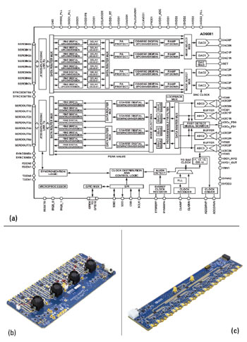
Figure 4 AD9081 MxFE functional diagram (a) QUAD MxFE prototyping system (b) and 16 Tx/16 Rx calibration board (c).
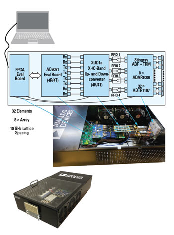
Figure 5 X-/Ku-Band phased array prototyping system.
Development platforms with high performance mixed converter front-ends (MxFE) can aid the design and implementation of a DBF array. They reduce engineering development and time to market for radar designers who need performance, optimized SWaP-C and high reliability. Using the high sampling rates of the latest generation data converters, the platforms support development of direct sampling receivers, shifting the design emphasis from the RF to embedded DSP on the converter. The DSP offloads the processing previously done by the FPGA, which maximizes the efficiency of system processing. These MxFE platforms can be used alone or as part of larger subsystem and system development solutions.
Analog Devices has developed a development platform for L-, S- and C-Band DBF phased arrays. The reference design has 16 transmit (Tx) and 16 receive (Rx) channels and contains four AD9081 MxFE direct RF sampling transceivers (see Figure 4a). The MxFE’s comprise RF front-ends, DSPs, high speed data interfaces and support circuitry including clocking, filtering and power. The Quad MxFE prototyping system is an evaluation platform for multi-chip synchronization, system level calibration, beamforming and other signal processing algorithms. A separate 16 Tx, 16 Rx calibration board (see Figure 4c) is also available to support developing system calibration algorithms to demonstrate power-up phase determinism as well as system performance improvements from a multichannel architecture. The Quad MxFE platform shows how noise and spurious improvements can be achieved when combining channels, with measurements showing approximately 10 dB improvement in noise density and improved spurious performance, resulting in better dynamic range with the combined channel architecture.4
This platform helps AESA designers meet several needs: 1) validating new beamforming technology for phased array radar, 2) offering a reference design for a complete system solution and 3) providing a software platform for customers to develop proprietary IP before their own custom hardware is available. This platform represents a multichannel system environment that engineers can work with to extrapolate to larger phase arrays. All these features help reduce time to market.
The element spacing at L- and S-Band makes it feasible to fit the electronics of a direct RF sampling architecture into every element using current transceiver technology and direct sampling converters. As noted, this becomes challenging as the radar’s frequency moves to X- and Ku-Band. Here, hybrid architectures are more practical.
For X- and Ku-Band frequencies, Analog Devices developed a second prototyping platform (see Figure 5), which uses a 4:1 beamformer IC (BFIC) to reduce the receiver/exciter count by four and provide additional space for the RF electronics. The platform is a testbed for demonstrating hybrid beamforming and implementing system calibrations and beamforming algorithms.5 It integrates eight, four-channel analog BFICs (ADAR1000) and 32 Tx/Rx modules (ADTR1107), one for each ADAR1000 channel. This is followed by RF up- and down-conversion between L-/S- and X-/Ku-Band (ADXUD1AEBZ), which feeds an AD9081 MxFE evaluation board. The platform also has a snap-on antenna board with 10 GHz lattice spacing.
SUMMARY
This article described the evolution of radar and the analog and DBF architectures used with AESAs. The benefits of full elemental DBF and the practicalities limiting their implementation have been compared to the hybrid subarray, which provides a practical option when DBF is not feasible.
Development platforms for both hybrid and DBF arrays facilitate the evaluation of disruptive concepts and technologies and shorten development cycles. Analog Devices has developed two such platforms for systems from L- to Ku-Band. They can help designers gain system insights that lead to better designs and shorter development time.
References
- R. Cariou, “Le Traitement Du Signal Radar: Détection et interprétation de l’écho radar,” Dunod, web: www.dunod.com/sites/default/files/atoms/files/9782100577972/Feuilletage.pdf.
- P. Delos, “An interview with Analog Devices Discussing RF Electronics for Phased Array Applications,” 2019.
- G. Stimson, H. Griffiths, C. Baker and D. Adamy, “Advantages of Digital Beamforming,” An Introduction to Airborne Radar, Third Edition, Institute of Engineering and Technology, 2014, pp. 133.
- P. Delos, M. Jones and H. Owens, “A Measurement of Distributed Direct Sampling S-Band Receivers for Phased Arrays,” pp. 5-7.
- P. Delos, S. Ringwood and M. Jones, “Hybrid Beamforming Receiver Dynamic Range Theory to Practice,” pp. 1-2.