
The article “The Open RAN System Architecture and mMIMO,” published in the November 2021 issue of Microwave Journal,1 described the open RAN (O-RAN) architecture and the split between the distributed unit (DU) and radio unit (RU) chosen by the O-RAN Alliance.2 This article expands the discussion of the RU, focusing on the architecture and key requirements of the RU used for mMIMO. The article concludes with the design and initial measurement results of an RU for 5G band 77 using the AMD-Xilinx digital front-end (DFE) and Versal processor.
MMIMO RADIO UNIT
The principal elements that determine the performance of a mMIMO RU are the
- Antenna — all parameters related to the radiation layer
- RF signal chain — parameters primarily related to the RF transceiver
- Product — Additional elements contributing to the performance of the RU
- Mechanical and thermal design and the external operating environment.
Each will be described in this section.
Antenna
The performance of an antenna in the RU is characterized by its gain and equivalent isotropic radiated power (EIRP), sidelobe levels, steering angle and elevation tilt.
Gain and EIRP — The maximum achievable gain of the mMIMO panel determines the maximum transmit power that can be directed to a specific user, where the EIRP is directly related to the gain of the antenna array. When receiving a signal from the user, the corresponding measure is equivalent isotropic sensitivity.
Gain comes at a price. To achieve higher gain, the antenna must have a larger active area, i.e., the size of the panel increases with gain. As the gain increases, the beamwidth decreases, which is intuitively expected as the antenna focus increases. With a limited number of transceivers, the steering—the azimuth or elevation range a beam can steer from boresight—decreases for a given maximum sidelobe level. The antenna design depends on the deployment environment and desired steering range. For a typical macro base station, a horizontal steering range up to ±60 degrees is desirable, depending on the minimum beamwidth. A vertical steering range of ±10 degrees or less from boresight is typically sufficient.
Sidelobe levels (SLL) — mMIMO and RU performance depend on the sidelobes generated by the antenna radiation layer. Today’s O-RAN mMIMO systems aim to limit sidelobe levels to below -10 dB across the whole sphere, particularly the horizontal and vertical steering ranges. A sidelobe that is not actively suppressed means power is also transmitted in the directions of the sidelobe, taking power from the desired direction. While active suppression techniques can reduce sidelobe levels, they also reduce the power in the main lobe.
Signals radiated from the sidelobes can cause interference in the unintended directions, with horizontal sidelobes interfering with adjacent sectors and vertical sidelobes interfering with adjacent cells. Both the upper and lower sidelobes should be considered. Upper sidelobes can reach into another cell when the main beam is steered downward, and the ground reflection of a lower vertical sidelobe can have a similar effect.
When receiving, power may come through a sidelobe from unwanted directions. Even though the DU can compensate for this, compensation typically increases the noise level of the remaining signal.
Steering — The ability of the RU to direct a beam away from boresight while keeping the SLLs low defines the steering range. Sidelobes tend to increase as the beam is directed away from boresight. Vertically, the steering range is often limited by a grating lobe, which causes the SLL to exceed the specified limit.
Typical values for the dynamic steering ranges for an RU with 64 transmit and 64 receive elements (64T64R) with SLLs ≤ -10 dB are ±45 degrees horizontal and ±5 degrees vertical. For 32T32R RUs with only two-element subarrays per column, the vertical steering range is less. For most macro base stations, ±2 degrees is sufficient.
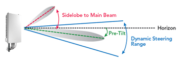
Figure 1 Antenna beam vertical steering and pre-tilting.
Electrical pre-tilt — Macro base station RUs are often installed at elevated sites. From the viewpoint of the antenna, the user traffic is coming mostly from below the horizon. Since the vertical steering range is limited, antennas are often installed with a pre-tilt, implemented either mechanically or with a linearly progressing phase difference between the elements in the subarray (see Figure 1). Pre-tilt is commonly used with RUs with 32 transceivers or less.
Remote electrical tilt (RET) — RET enables the pre-tilt of the RU to be adjusted remotely. This is easily done by remotely adjusting phase shifters built into the subarrays or by using a motorized bracket that tilts the antenna. Like pre-tilting, RET is typically used only for RUs with 32 or fewer transceivers because they have limited vertical steering compared to RUs with a larger number of transceivers.
RF Signal Chain
Connecting to the antenna, the RF signal chain influences the performance of the RU through its transmit power, bandwidth and error vector magnitude (EVM).
Conducted RF power — The transmit power supplied by the power amplifier (PA) to the antenna, known as the conducted RF power, determines the limits of coverage and cell capacity. The transmit power and antenna gain determine the maximum propagation loss the link can accommodate. In a mMIMO RU, the RF power is distributed over several spatial streams as well as resource blocks (RB). For larger cells, higher PA power increases the downlink capacity of the cell.
Bandwidth — Three bandwidths are associated with RUs. First, the occupied bandwidth (OBW) is the aggregate bandwidth over which the RU actively transmits and receives. Synonymous with the utilized spectrum, the OBW is the sum of all the active carrier bandwidths and the upper limit the RU can handle. Second, the instantaneous bandwidth (IBW) of the RU is defined from the left edge of the lowest frequency carrier to the right edge of the highest frequency carrier. Last, the operating bandwidth is the bandwidth supported by the RU, typically referred to as the operating band. For spectrum agility, operators desire the RU’s IBW to support the entire band, i.e., the IBW should equal the OBW.
EVM — EVM is a measure of the distortion within a modulated signal and indicates the linearity of a transmit chain. In more efficient modulation schemes, such as 256- or 1024-QAM, more bits are mapped to a subcarrier, which requires increasingly cleaner transmit signals compared to lower-order modulation. Nonlinearities in the transmit chain add noise to the transmit signal, causing the constellation points to deviate from their ideal values, which makes demodulating the transmitted information in the receiver more challenging.
Product
In addition to the antenna and RF signal chain, these aspects of the design contribute to the performance of a mMIMO RU system: the number of data streams, phase and amplitude control and calibration, fronthaul, programmability, security and power consumption.
Number of data streams — The objective of the mMIMO architecture is to increase data capacity by tapping the spatial domain. If propagation conditions enable users to be separated, the number of spatial streams the RU can handle becomes the limitation. For a 64T64R RU, being able to handle 16 layers downlink and eight layers uplink is typically considered enough. For a 32T32R RU, the number of spatially resolvable signals will be less. To reduce fronthaul data rates, 32T32R RUs often use eight downlink and four uplink streams.