
This application note demonstrates use of HYPERLABS’ broadband coaxial components as general-purpose analog signal processing components for the generation of novel time-domain waveforms. The HL9474 6 dB resistive power divider and HL9462 Z-matched pick-off tee are demonstrated as lossy broadband summing networks. The HL9404 broadband balun is demonstrated as a pulse inverter and 180° signal splitter. The HL5567 PAM4 encoder is used to combine two pseudorandom binary or bit sequence (PRBS) patterns into PAM4 signaling. Utilizing the basic arithmetic functions of addition, inversion and subtraction, together with a time delay, a wide variety of novel broadband waveforms are generated.
This application note builds on prior work reported in Picosecond Pulse Labs (PSPL) Application Note AN-20a[1]. In the referenced note, Jim Andrews, Ph.D. used PSPL pulse generators together with PSPL passive components to produce a variety of novel waveforms. A similar set of waveforms are demonstrated at higher bandwidths in this application note utilizing HYPERLABS’ industry leading broadband passive components.
Applications
The waveforms demonstrated in this application note are useful for a variety of applications ranging from ultrawideband (UWB) imaging to data communications.
UWB MONOCYCLE
Starting with a 20 ps full width half max (FWHM) single-ended positive impulse, a UWB monocycle is generated. First, HL9404 broadband balun is used to create a differential impulse. Next, the negative impulse is delayed by 20 ps and added to the positive impulse using an HL9474 resistive power divider (see Figure 1). The measurements of the various pulses made by the block diagram in Figure 1 can be seen below (see Figures 2 to 5).
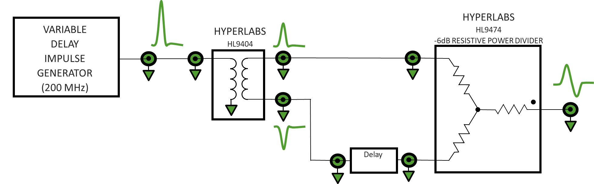
Figure 1. Block diagram of UWB monocycle generator
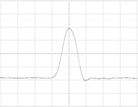
Figure 2. Input impulse at 100mV/div & 20ps/div
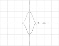
Figure 3. HL9404 outputs at 100mV/div & 20ps/div
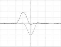
Figure 4. Negative balun output delayed by 20 ps
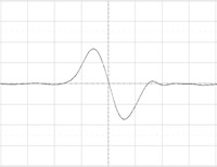
Figure 5. Summed output at 50mV/div & 20ps/div
PRE-DISTORTED PULSES
Using a resistive power divider, a narrow impulse can be added or subtracted from a rectangular pulse to create various waveform defects, such as precursor, overshoot and trailing edge undershoot. The techniques demonstrated below can be used to pre-distort waveforms and compensate for distortion products generated elsewhere in the system.
Once again, the HL9404 broadband balun was used to create a differential impulse. The HL9462 Z-matched pick-off tee was used as a weighted (unequal) summing network (see Figure 6).
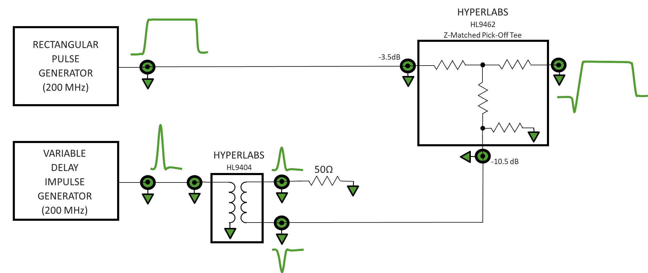
Figure 6. Block diagram of pre-distorted pulse generator
A 20 ps wide negative impulse was summed with a 200 ps wide rectangular pulse to create the first series of pre-distorted pulse waveforms. Each pulse source was set to 400 mVp-p amplitude and 200 MHz repetition rate. The input pulses are shown in Figure 7 and Figure 8. The relative delay between the impulse and rectangular pulse generators was adjusted to position the effect of the impulse at various locations on the rectangle pulse.
The single-ended insertion loss of HL9404 broadband balun is typically 6 dB. The pick-off port of HL9462 typically has 10.5 dB loss compared to 3.5 dB loss at the thru port, a difference of 7 dB. The impulse is thus attenuated by ~13 dB relative to the rectangular pulse (6 dB in the balun and 7 dB in the pick-off tee) resulting in ~20 percent precursor (see Figure 9). By increasing the relative delay of the impulse generator, the negative impulse can be re-positioned to give an interference drop-out in the middle of the rectangle pulse (see Figure 10), or a trailing edge undershoot (see Figure 11).
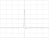
Figure 7. Input impulse. 100mVdiv & 100ps/div
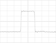
Figure 8. Input rectangle pulse. 100mV/div & 100ps/div
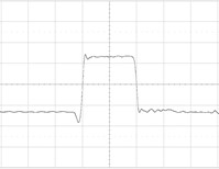
Figure 9. Rectangular pulse with 20% precursor. 100mV/div & 100ps/div
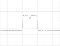
Figure 10. Rectangular pulse with interference drop-out. 100mV/div & 100ps/div
To generate positive going aberrations on the rectangle pulse (see Figures 12 and 13) the generator is simply re-configured connecting the positive output of the balun to the pick-off port (see Figure 14).
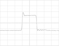
Figure 12. Rectangular pulse with 20% overshoot. 100mV/div & 100ps/div
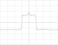
Figure 13. Rectangular pulse with 20% Interference spike.100mV/div & 100ps/div
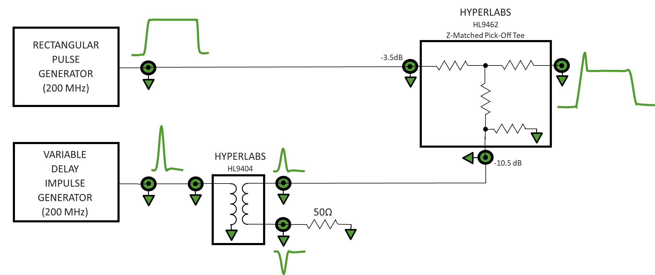
Figure 14. Block diagram of pre-distorted pulse generator
By adjusting the impulse delay, the impulse can be positioned to generate an overshoot as in (see Figure 12), or an interference spike (see Figure 13).
NOISE LIKE PULSES (NLP)
A noise like pulse (NLP) is generated by summing a relatively high amplitude and narrow impulse on top of a rectangular pedestal or lower bandwidth gaussian pulse. For this demonstration, an HL9474 6 dB power divider is used to sum the two input signals. A 6 dB attenuator is inserted in the path of the pedestal pulse to give the impulse 2x weighting over the pedestal.
Later in this application note, similar 2x weighted summation functionality is demonstrated using the HL9462 Z-matched pick-off tee without need for an external attenuator. A block diagram of the NLP generator system is depicted in Figure 15.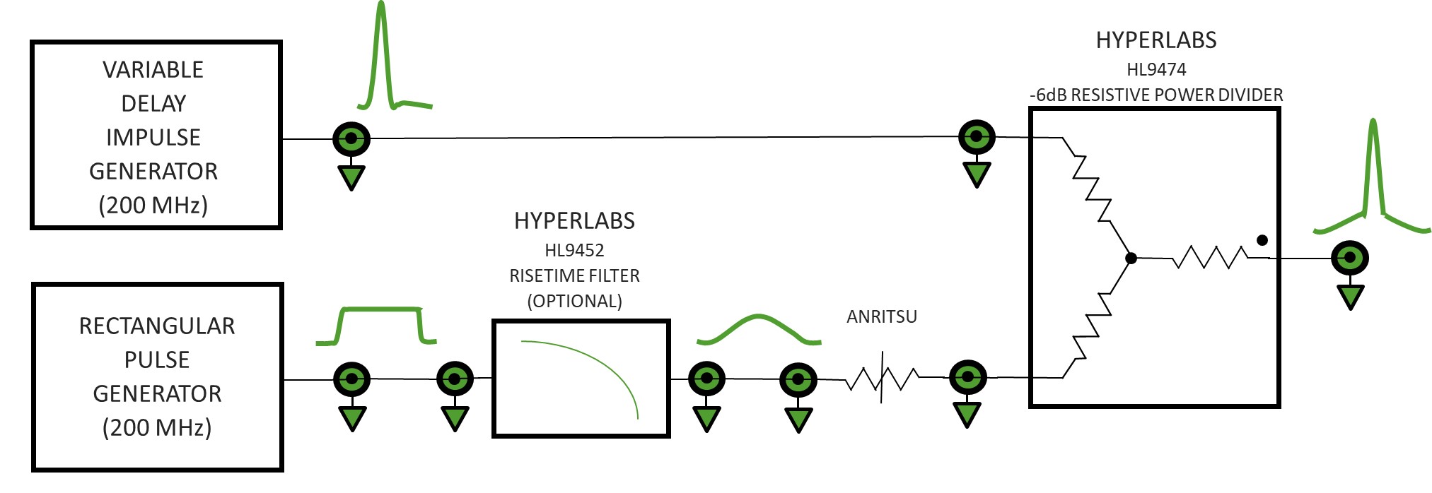
Figure 15. Block diagram of NLP generator
The input signals are a 20 ps FWHM impulse and a 500 ps wide rectangular pulse, both running at 200 MHz repetition rate (see Figure 16).
First, the signals were added without a lowpass filter in the system, resulting in a rectangular pedestal NLP (see Figure 17).
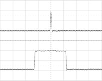
Figure 16. Input signals for NLP generator. 200mV/div & 200ps/div
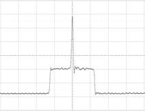
Figure 17. NLP with rectangular pedestal. 50.V/div & 200ps/div
Next, an HL9452-200 risetime filter was inserted in the path of the pedestal pulse. The HL9452-200 is a transition time converter. It converts the fast risetimes and fall times of the rectangular pulse source into 200 ps transitions, 10 to 90 percent, (see Figure 18 for result).
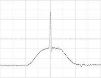
Figure 18. NLP with pseudo-gaussian pedestal pulse. 50mV/div & 200ps/div7
100 Gb/s PAM4 ENCODING
Two binary serial data streams can be summed to generate 4-level pulse amplitude modulation (PAM4). In this broadband modulation scheme, the amplitude of the most significant bit (MSB) is 2x the amplitude of the least significant bit (LSB). HYPERLABS’ HL5567 PAM4 encoders are a single component solution, perfectly suited to perform PAM4 encoding. Using two nearly equal amplitude nonreturn to zero (NRZ) serial data streams, the LSB is connected to the pick-off port and the MSB is connected to the input (see Figure 19).
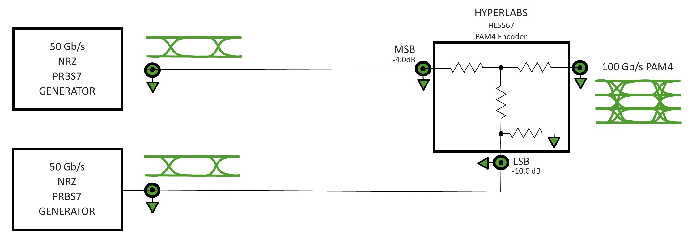
Figure 19. Block diagram of PAM4 encoder test
In Figure 20, two 50 Gb/s serial data streams were combined using an HL5567 PAM4 encoder to create a 100 Gb/s PAM4 signal. The LSB and MSB data patterns were 7th order pseudorandom binary sequences (PRBS7). A PRBS7 data pattern is 127 bits long. The LSB data pattern was delayed by 39 bits relative to the MSB data pattern. The entire pattern length of each input signal can be found in Figure 20. Eye diagrams of the input signals are shown in Figures 21 and 22.
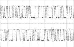
Figure 20. Input data patterns, 50 Gb/s, PRBS7, LSB (top), MSB (bottom). 200mV/div & 255ps/div
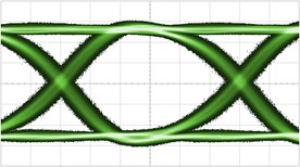
Figure 21. LSB input eye diagram, 50 Gb/s, PRBS7. 75mV/div & 3.35ps/div
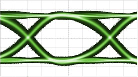
Figure 22. MSB input eye diagram, 50 Gb/s, PRBS7. 75mV/div & 3.35ps/div
Output signals representing each input individually and in combination were examined. First, each input signal was connected to the HL5567 individually with the opposite input terminated into 50Ω. The corresponding binary output waveforms were captured and appear in Figure 23 (top and middle). Finally, both input signals were connected simultaneously and the combined PAM4 output waveform was captured and can be seen in Figure 23 (bottom). Output eye diagrams are presented in Figures 24 to 26.
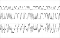
Figure 23. Output data patterns, LSB (top), MSB (middle), LSB+MSB (bottom). 200mV/div & 255ps/div
The HL5567 PAM4 encoder produces high quality 100 Gb/s PAM4 waveforms when driven from two high quality 50 Gb/s PRBS7 binary patterns (see Figure 26). Minor pattern dependencies were observed when tested at different bit shift values; results will vary when used with real world data.
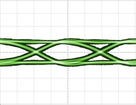
Figure 24. 50 Gb/s output eye diagram. LSB port driven, MSB port terminated into 50Ω.
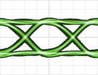
Figure 25. 50 Gb/s output eye diagram. MSB port driven, LSB port terminated into 50Ω.
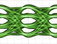
Figure 26. 100 Gb/s PAM4 output eye diagram. LSB and MSB ports driven. 71mV/div & 5ps/div
It is important to keep in mind that the HL5567 PAM4 encoder is a resistive passive network. This feature allows any data pre-emphasis to pass through the device without any non-linear effects.
CONCLUSION
HYPERLABS’ broadband coaxial components provide arithmetic functionality at very high bandwidths. The HL9404, HL9462, HL9474 and HL5567 were demonstrated as general-purpose analog signal processing components for the generation of novel time-domain waveforms. Addition, inversion, subtraction and weighted summation were demonstrated.
PHOTOS
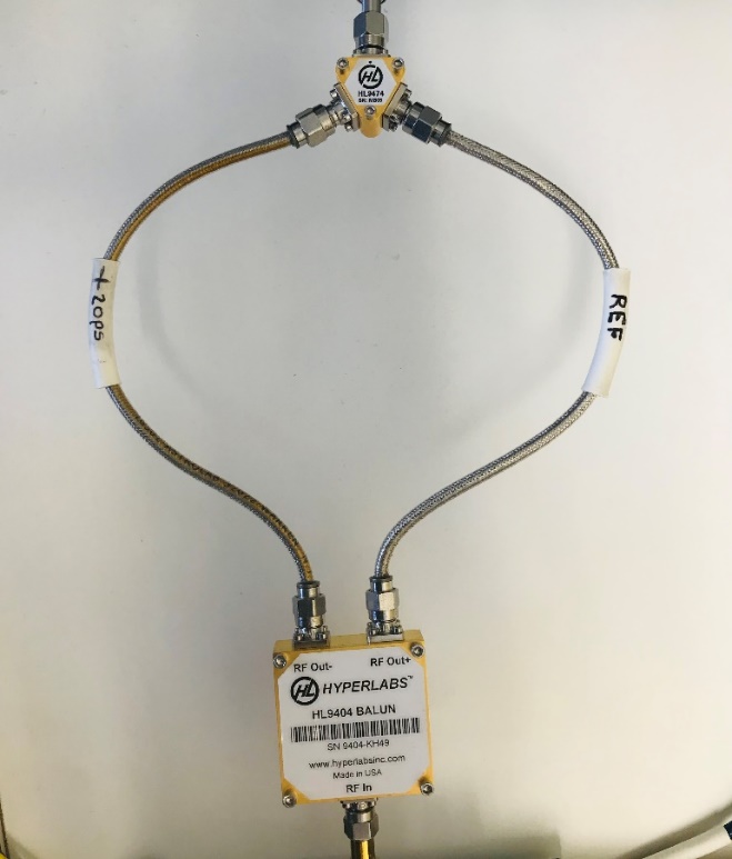
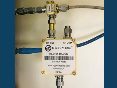
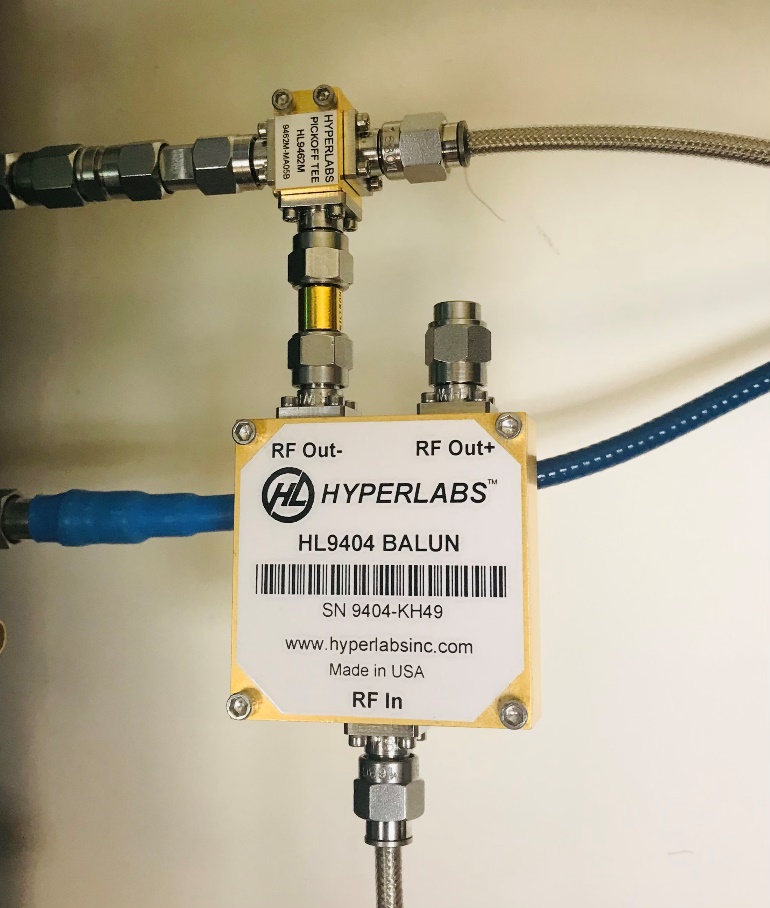
UWB monocycle generator
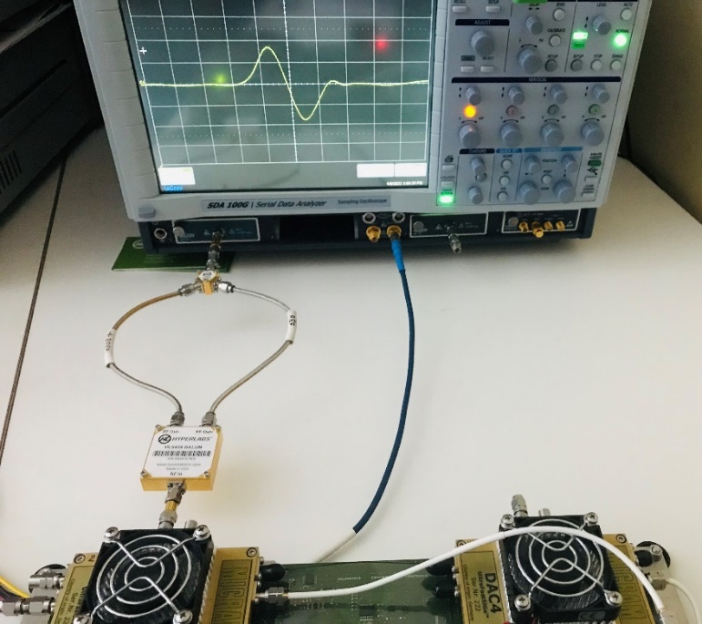
Monocycle generator together with LeCroy SDA100G sampling oscilloscope, SE-50 sampling modules and dual-channel micram DAC4 signal source
Pre-distorted pulse generator