
Another example is the project at the University of Florida. A team of researchers, professors and students at University of Florida led by John W. Conklin and Peter Wass (Department of Mechanical & Aerospace Engineering) in collaboration with Professor Dr. Guido Mueller (Department of Physics) has been awarded a $12.5 million NASA contract to build and test a prototype of a charge management device for the space mission by July 31, 2025 (see Figure 2).
This charge management system is a ultraviolet (UV) light device that can monitor electrical charges of the free falling test masses inside the three LISA spacecraft. These test masses are cubes made of a gold-platinum alloy, each with an edge length of 46 mm and a weight of 2 kg. The charge management device will shine the appropriate amount of UV light on the test masses to keep their charges at zero, preventing unwanted motion.6 The job of the University of Florida team is to ensure nothing but gravitational waves move the particle masses and that the discharge of the test masses does not generate any undesirable side effects.6
Two internal test masses per spacecraft are used, each one dedicated to a single interferometry arm.7 Every spacecraft uses high-precision heterodyne laser interferometry to measure extremely small distance variations (pm to nm) between the test masses caused by gravitational waves. All test masses inside the three spacecraft will be in free fall along the lines of sight between the spacecraft and serve as inertial sensors for estimating position.4 The test masses are shielded by the containing spacecraft against external perturbations. Capacitive sensors surrounding each test mass will monitor their positions and orientations with respect to the spacecraft. To keep each satellite centered on the test masses the tiny orbital and attitude corrections will be determined by a drag-free attitude control system using the measurements of inertial sensors. This system of regulating the satellite position enables new missions which, for example, will also be used to measure the effects of climate change on the planet in the future. LISA will detect gravitational waves with three independent interferometric combinations of the light travel time measurements between the test masses along the sides of a triangular configuration.7
Coaxial Cables from SSB-Electronic Evaluate Compliance with the Project Requirements
The coaxial cables of SSB-Electronic are used at the PSSL of the University of Florida for test stands that will evaluate the LISA charge management system under the NASA contract. According to Simon Barke, one of the technical directors of the PSSL, the success of the PSSL team, but also of the entire LISA mission, depends on the phase stability of high frequency signals that help track changes in distance between the test masses. Gravitational waves are expected to affect this distance by just a few picometers. Changes in distance will be translated to slow (mHz) phase shifts on the order of microradians in a 20 MHz electrical detection signal. The phase of a 20 MHz signal will be tracked with sub-picosecond precision over hours.
Spurious phase noise caused by any device in the measurement chain would spoil these delicate measurements. One limiting noise source is electrical cables. Temperature fluctuations can change the length and electrical properties of the cable, which results in a phase change of the signals. For the LISA project, cables must be used that will not change the phase of an electrical signal over temperature.
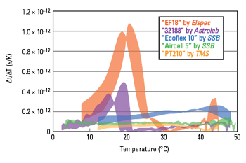
Figure 3 Phase stability of five cables. Source: Simon Barke.8
To evaluate the phase stability of different test cables, the change in signal arrival time (Δt) over temperature change (ΔT) per meter cable is measured.8 A 2 GHz signal is split and passed through the cable under test and a reference cable of equal design and length. With a special device, a 28 cm section of the cable under test is heated and cooled in the range of 5°C to 50°C, which is the temperature range expected inside LISA spacecraft.8 The phase of both signals is measured after mixing them down to a more convenient frequency of 1.6 GHz. Five candidate cables of three different types are used for the test, distinguished by different dielectric layers: polytetrafluoroethylene (PTFE), low density polyethylene (PE) or TF4™ (proprietary fluorocarbon dielectric material from the company TMS).
Figure 3 shows the results of measurements to evaluate the phase stability of the test cables. The width of each trace reflects the range of the calculated timing stability coefficients that are different for cooling and heating periods.
The results show that the cables with dielectrics based on PTFE exhibit an inherent, non-linear phase change when the material passes through the temperature range of 15°C to 25°C. These cables are therefore unsuitable for the LISA project.
The coaxial cables from SSB-Electronic using a PE dielectric, especially the cables of the Aircell 5 series, offer a flat temperature coefficient of maximum. Δt/ΔT = 1.4 × 10e-13 over a wide temperature range from 5°C to 50°C. These are among the most phase stable cables in the industry. Specifications of the cables under test, including the measured maximum timing stability coefficients per meter, are summarized in Table 1.
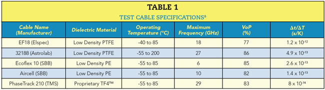
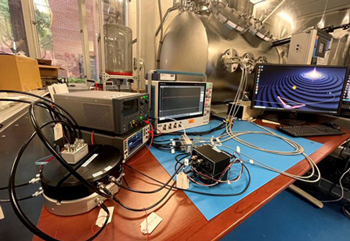
Figure 4 Test stand at PSSL. Source: University of Florida.
Based on the measurement results, PSSL chose Aircell 5 cables for use in a test stand to evaluate the LISA charge management system under the NASA contract. Aircell 5 cables are used to carry electrical pulses from a frequency reference and photomultipliers tubes to Moku:Lab phasemeters. Figure 4 shows the setup of the test stand at the PSSL, University of Florida. The cables enable confirmation that the light pulses emitted by the charge management system and detected by the photomultiplier tubes conform to the strict timing requirements of the LISA project.
CONCLUSION
Coaxial cables from SSB-Electronic are used in current basic research projects and are also suitable for space applications due to their phase stability. They are an attractive alternative to TF4 cables, especially for ground support equipment and test stands.
References
- Laser Interferometer Space Antenna, ESA, NASA, https://lisa.nasa.gov/.
- LISA Consortium, Web: www.lisamission.org/.
- “Almost 1.5 Million Euros in Funding for Participation in ESA Space Mission,” Listen to the Universe, University Hamburg, Web: https://www.uni-hamburg.de/newsroom/presse/2020/pm47.html.
- M. Gohlke, “A Highly Symmetrical Heterodyne Interferometer for Demonstrating an Optical Reading of the Inertial Sensors of the Space-based Gravitational wave Detector LISA,” Humboldt-Universität zu Berlin, Web: www.physics.huberlin.de/en/qom/publications/pdfs/DA_Martin_Gohlke.pdf.
- Max Planck Institute for Gravitational Physics, “LISA,” Web: www.aei.mpg.de/40458/lisa.
- D. Ivanov, “UF Awarded NASA Grant for Space Exploration Technology,” The Gainesville Sun, January 2021, Web: www.gainesville.com/story/news/2021/01/09/uf-given-nasa-contract-build-lisa-cms-space-exploration-technology/4125143001/.
- K. Danzmann, “LISA Laser Interferometer Space Antenna, A Proposal in Response to the ESA Call for L3 Mission Concepts,” Web: www.elisascience.org/files/publications/LISA_L3_20170120.pdf.
- S. Barke, “Inter-Spacecraft Frequency Distribution for Future Gravitational Wave Observatories,” Ph.D. Thesis, Max Planck Institute for Gravitational Physics (Albert Einstein Institute), 2015.