
Substrate integrated waveguide (SIW) is a bridge between planar and non-planar transmission lines. It inherits the merits of both metallic waveguides and planar structures. Non-planar rectangular or circular waveguide can handle high power and provide high selectivity but weighs more and is relatively expensive, where planar transmission line is light weight and producible using low-cost mass production techniques. It cannot, however, withstand high power and generally has higher losses. SIW filters, such as cross coupled filters, defected ground structure (DGS) based filters, metamaterial-based filters, tunable filters and filters on new materials are reviewed along with bandwidth enhancement, size reduction and selectivity improvement.
The electromagnetic spectrum is heavily crowded with wireless signal frequencies. Microwave and mmWave filters are in high demand to enable the reception of desired signals or reject unwanted ones. Bandpass filters are the most popular type for most common applications such as communication systems. They are also the most challenging to design and construct.
An RF filter designer must balance conflicting requirements. For example, achieving high selectivity demands more resonators; but this results in increased insertion loss, which is proportional to the number of resonators. The design parameters of a filter include insertion loss, return loss, group delay, unloaded quality factor, loaded quality factor, external quality factor, cost and skirt selectivity. An RF engineer must balance performance parameters to develop an optimum filter, however, the biggest tradeoff is between performance requirements and cost.
The loss mechanism is another important consideration. Along with the physical and electrical parameters, it depends on the filter’s resonant mode behavior. A particular resonance behavior is associated with the electric and magnetic field distribution of that mode, which in turn is related to the loss mechanism. A resonator can support numerous resonant modes. The excitation mechanism, filter structure and resonant frequency determine the number of modes. Multimode resonators play an important role in determining filter size and insertion loss.
The development of a filter depends on the selection of a suitable transmission line or waveguide technology. A planar microstrip filter weighs less than a waveguide filter, but its quality factor is poor. A non-planar rectangular waveguide filter has an excellent quality factor and handles greater power but is heavier and occupies a larger volume. A fusion of these two technologies by K. Wu in 2001 led to the development of substrate integrated waveguide technology.¹ SIW is popular due to its high quality factor, high-power handling capability, low-cost and low loss.
SIW CONCEPT
SIW is a planar waveguide that can be fabricated using printed circuit board or low temperature cofired ceramic (LTCC) technologies. It is constructed by inserting two rows of metallic via posts into a dielectric substrate with a top and bottom metal lining (see Figure 1).1
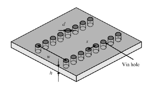
Figure 1 SIW configuration.2
The SIW structure supports only the transverse electric mode of propagation.2 The propagation characteristics of the SIW TEn0 mode is like that of the rectangular waveguide TEn0 mode. Absence of a transverse magnetic mode makes SIW an appropriate choice for the design of bandpass filters. The characteristics of SIW are thoroughly discussed by Xu and Wu,2 and by Deslandes and Wu.3 A review of SIW is provided by Kumar and Raghavan.4
The frequency zone of interest for the TE10 mode is3

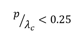
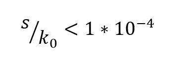
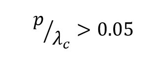
where k0 is the wave number in free space.
Equation (1) states that the period length, p, should be larger than the via diameter, d. Equation (2) must be satisfied to avoid band gap effect. Equation (3) ensures that leakage losses can be neglected. For mechanical rigidity, Equation (4) must be satisfied. Figure 2 shows the zone of interest for SIW in the plane of p/λc and d/λc.
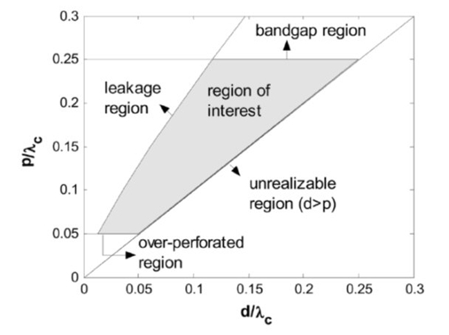
Figure 2 Zone of interest for SIW.3
Rectangular waveguide and SIW parameters are related by5
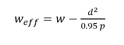
where w is the SIW actual width, weff is its effective width, d is the diameter of the post and p is the pitch.
A more accurate relationship is given by2

The method of lines provides another empirical relationship6

where
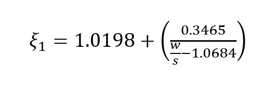


Soundarya and Gunavathi analyzed SIW impedance and phase constants.7
SIW TRANSITIONS
Attention must be paid to interconnecting SIW with other planar circuits. The proper excitation of SIW components depends on the quality of these interconnections, or transitions. The basic interconnection of microstrip to SIW is tapering.8,9 Good return loss can be achieved using this type of transition (see Figure 3).
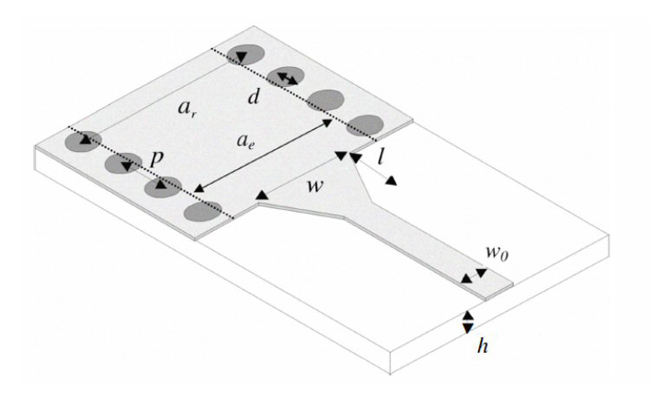
Figure 3 Microstrip to SIW transition.8
Yang et al.10 described an open-circuited transition between a microstrip line and SIW on an LTCC substrate in which energy was transferred to the waveguide through a via probe from the microstrip line. Abdolhamidi et al.11 developed a single-layer DC-decoupled SIW-to-microstrip transition using an interdigital configuration. Instead of a taper, an exponential transition from microstrip to SIW was developed by Sotoodeh et al.12 Transitions from SIW to other transmission lines such as co-axial lines and coplanar waveguide were summarized by Mallick et al.13 Another multi layered transition from SIW to Empty SIW (ESIW) was also proposed.14 Kordiboroujeni and Bornemann15 described a microstrip to SIW transition where two additional vias were implemented in the regular taper to provide excellent results. A new design formula was also proposed by the authors.
SIW RESONATOR
SIW has been used for the design of filters from Gigahetrz to Terahertz. The essential structure of any filter is the resonator. The unloaded quality factor (Qu) depends on the selection of transmission line technology.16 Figure 4 visualizes the relationship between insertion loss, volume and cost of various RF resonators.
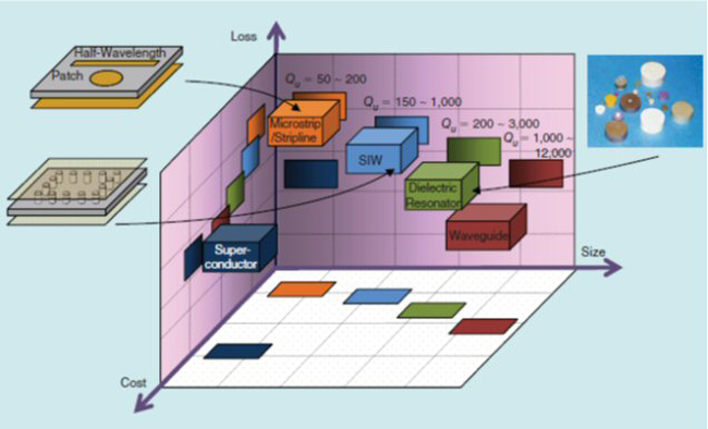
Figure 4 Comparative loss, size and cost of various resonators.16,17
For a given resonator, different excitations may lead to different modes, which provide different unloaded quality factors. Figure 5 shows different SIW cavity resonator excitation techniques. Center coupling provides the highest Qu.
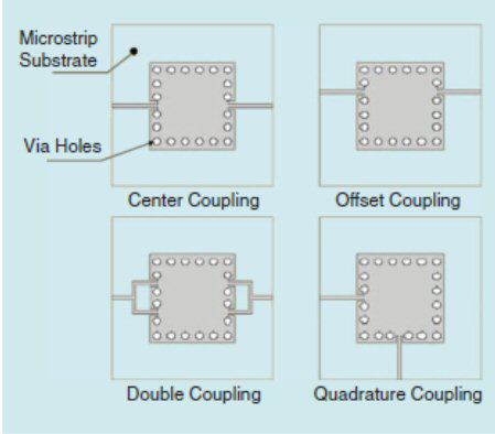
Figure 5 Different SIW resonator coupling methods.18
Qu can be obtained from the S-parameters by19,20
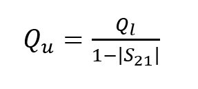
where S21 is the transmission coefficient and Ql is loaded quality factor, which is given as
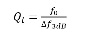
where f0 is the center frequency and f3dB is the 3 dB bandwidth of the filter.
Different classes of SIW filters and their transitions were summarized by Bozzi et al.21 In 2003, D. Deslandes and Ke Wu developed the first SIW filter by integrating planar circuits and waveguide filters.22 A PI network modeled the inductive posts. Post dimeters were calculated with theory proposed by Marcuvitz.23 The PI network was converted into an equivalent K inverter.24 Direct coupled waveguide resonators are compatible with this SIW technique.25-36 This design exhibits a standard Chebyshev response.
SIW CROSS COUPLED FILTERS
An overview of cross coupling was summarized by J.B.Thomas.37 High filter selectivity depends on the location of the finite transmission zeros (FTZs). One way of producing FTZs is to use the cross coupling concept which provides multiple paths for the signal to flow. Whenever two different signal paths have same magnitude but opposite phase, they cancel each other and an FTZ is generated on the imaginary axis of the complex frequency plane. Chen and Wu38 developed a cross coupled filter with stronger negative coupling between resonators 1 and 4 as shown in Figure 6. Positive coupling exists between resonators 1 and 2,2 and 3 and 3 and 4. Magnetic post wall irises provided positive coupling; and, a structure made up of a magnetic coupling iris and a microstrip line with a pair of metallized via-holes provided negative coupling. They developed two K-Band cross coupled SIW bandpass filters, without and with source-load coupling, having a center frequency of 20.5 GHz and respective bandwidths of 700 and 800 MHz.
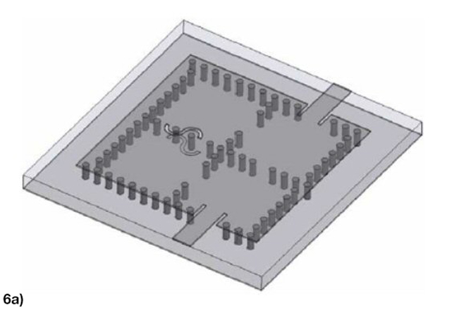
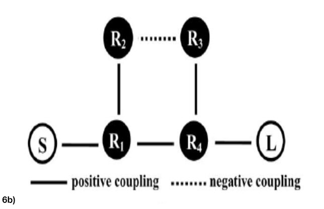
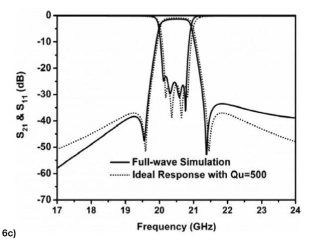
Figure 6 K-Band SIW cross coupled filter without source-load coupling: geometric configuration (a), topology (b) and filter response (c).37
Chen and Wu39 demonstrated a Ka-Band asymmetric response bandpass filter. They used a higher order resonant mode (TE102) to attain negative coupling. The filter had a center frequency of 35 GHz with a 1.3 GHz bandwidth. Conductor backed coplanar waveguide (CBCPW) was used to excite the filter.
Compared to the conventional Chebyshev response, quasi elliptic and elliptic filters have sharp skirt selectivity. Chen et al.40 exploited this property.
An SIW transverse bandpass filter with a mutated doublet was proposed by Li et al.41 It contained two resonators not directly coupled to each other; instead, the source and load were coupled directly to produce two transmission zeros resulting in high skirt selectivity.
SIW FILTERS WITH DGS
Any geometrical slot implanted in the ground plane is called a DGS.42,43 It can be either a unit cell or periodic (see Figure 7).
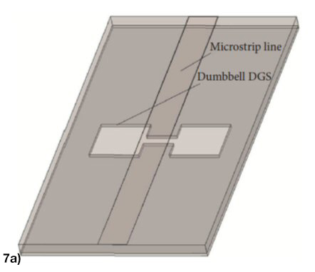
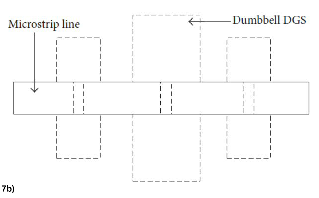

Figure 7 Unit cell – Dumbbell DGS (a), horizontally periodic DGS (b) and vertically periodic DGS (c).43
The DGS is included in the ground extension along transmission line (microstrip, coplanar waveguide or CBCPW).44-48 The defects on the ground plane disturb the current distribution of the ground plane; which, in turn, affects the current distribution on the transmission line. This is because the ground plane defect changes the effective capacitance and inductance of the transmission line. A photonic band gap occupies a larger area, where the DGS is compact. It is also easy to design and fabricate. Various other DGS shapes are shown in Figure 8. These configurations offer higher slow wave factors, larger external quality factors and a wider stop bands with deeper rejection.
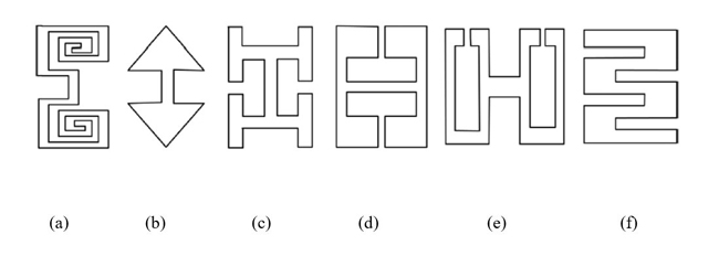
Figure 8 Different DGS configurations: spiral head (a), arrow head slot (b), “H” shape slots (c), square open loop with a slot in middle section (d), open loop dumbbell (e) and inter digital (f).42