
Open radio access networks (O-RAN) are transforming mobile networks. O-RAN is about the disaggregation of the traditional RAN system into the radio unit (RU), distributed unit (DU) and centralized unit (CU) components and their hardware and software platforms.1 O-RAN fosters innovation by involving more manufacturers in the development of the RAN infrastructure, enabling new entrants to compete and disrupt the market if they can offer a competitive edge. Ideally, the O-RAN specifications will create a broad RAN supplier ecosystem, where operators can pick and choose components from different suppliers and not be bound to a single company. The disaggregation of hardware and software enables virtualization, meaning large parts of the network functions become virtualized and can be run on commercial off-the-shelf hardware or general purpose processors. Virtualization also enables “cloudification,” where many functions are hosted by multiple servers, typically bundled in one or more data centers.
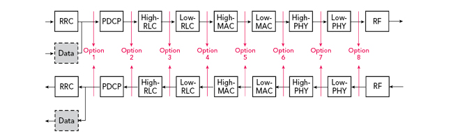
Figure 1 Functional split between the CU and DU.
For O-RAN networks to succeed and become accepted, the standardization of interfaces and proven interoperability are the keys to success. 3GPP has investigated different functional split options between the CU and DU (see Figure 1).2 The O-RAN ALLIANCE has chosen 3GPP split option 2 for the interface between the CU and DU and split option 7 as the DU to RU interface. The centralization of the packet data convergence protocol (PDCP) layer enables scaling with the user plane traffic load. The O-RAN ALLIANCE has chosen the so-called split option 2-2, enabling the separation of the U-plane from the other planes, while having a centralized radio resource controller and radio resource manager. For the interface between DU and RU, the O-RAN ALLIANCE has chosen an intra-physical layer (PHY) split, i.e., between the low PHY and high PHY.
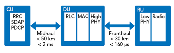
Figure 2 Network function partitioning into the CU, DU and RU.
The high-level functional partitioning into the CU, DU and RU is shown in Figure 2. The link between the RU and DU is referred to as the fronthaul, and the link between the CU and DU is referred to as the midhaul. Due to the various control loops within the system, different latencies can be tolerated. The most critical interface is the fronthaul, which typically tolerates latencies up to 160 µs. If a point-to-point connection is used to connect the RU to the DU, a distance between the RU and DU of up to 30 km can be supported.
As this article’s focus is the RU, the discussion is more on the O-RAN fronthaul interface and the corresponding architectural split. When selecting the fronthaul interface, the following aspects must be considered:
Transport Bandwidth — Referring to Figure 1, the required data rate reduces from the right (the option 8 interface between the PHY and RF) to the left. The chosen split provides a good compromise between flexibility and algorithmic differentiation, with a modest demand on the data rate.
Architecture Split — The split must reflect the intention of an O-RAN architecture: vendor neutral hardware and software. The radio’s performance is defined not only by the radio hardware, but also by the way the signals are processed. To be accepted by the market, an O-RAN system must deliver comparable performance to conventional single-vendor systems. The architectural split enables innovation and stimulates differentiation and, if possible, should not stipulate certain processing algorithms or preclude alternative processing techniques. The O-RAN ALLIANCE has chosen an interface that defines the radio hardware with clearly defined and understandable processing functions tightly controlled by the DU and its software.
Interoperability — Interoperability between different vendor systems is key for O-RAN to be adopted by the market. Therefore, the architectural split must provide an interface easily understood by any implementer, clearly described with no room for interpretation and rigorously tested for interoperability.
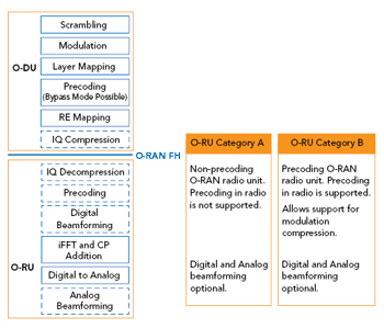
Figure 3 O-RAN architecture. Source: O-RAN Fronthaul Working Group.3
The O-RAN ALLIANCE has defined an interface referred to as the 7.2x split.3 In the 7.2x split, the O-RAN fronthaul interface resides between the resource element mapping in the DU and the time-frequency conversion in the RU, i.e., the inverse FFT (iFFT) and cyclic prefix (CP) addition in the downlink and CP removal and FFT computation in the uplink, respectively (see Figure 3). The dotted processing blocks in the figure are not mandatory for all RU categories. Precoding for certain RU categories can be done within the RU, in which case precoding in the DU is bypassed. For mMIMO radios, the interface foresees digital beamforming on the RU side. Digital beamforming is omitted for conventional radios, which typically have only a small number of transceivers. Additionally, the O-RAN ALLIANCE distinguishes between category A and B type O-RUs. The category B architecture supports MIMO precoding in the O-RU; category A does not. The category B O-RU provides support for modulation compression, a technique to reduce the fronthaul bandwidth by moving the modulation function to the O-RU.
In addition to the user traffic handled by the so-called U-plane of the fronthaul interface, O-RAN defines three other planes: the M-plane for handling management control data, the C-plane for handling near real-time control data and the S-plane for handling synchronization (frequency and time). The M-plane is primarily used for configuring the RU, reading out status information and handling errors and alarms.4 It is entirely based on the NETCONF protocol, an XML-based protocol to set and query the operation of a network device. It uses YANG as its data modeling language. Typical configuration data includes
- Setting up the carrier (e.g., the center frequency, bandwidth and power)
- Mapping the antenna layers
- Fully resetting the software of the RU
- Updating the O-RU software, as the M-plane supports downloading entire software images.
Typical parameters that can be queried concerning the O-RU state and general information are
- Physical structure of the antenna radiating panel
- Clock synchronization state
- Fronthaul interface version and information about supported C- and U-plane section types and extensions
- Boot state
- O-RU alarms and performance counters, such as the number of packets received AND number of U-plane data packets received on time, late or corrupt.
The radiating panel is modeled as a rectangular array of equally distributed and independently controlled radiating elements. This information is useful for the O-DU to compute the beamforming weights used to form the desired beams. The beamforming weights determine the direction and shape of the beam. Especially in mMIMO systems, a different set of beamforming weights is typically used for every time transmission interval; however, changes can occur as often as every OFDM symbol.
As mentioned, the O-RAN ALLIANCE supports the vision of disaggregated hardware and software. Therefore, it has defined the radio (O-RU) to be directed by the O-DU, where the algorithms for channel estimation, weight computations and near real-time user scheduling reside. The traffic associated with the provision of beamforming weights can be substantial and may be the same order of magnitude as the user plane traffic. Hence, different means of reducing the traffic are defined in the O-RAN specification.
For a cellular network to work properly, the radio units must be synchronized with an accuracy of ±25 ppb in frequency and ±1.5 µs in time. The O-RAN specification defines several means of synchronizing the RUs to the network, with the predominant method for synchronization the IEEE 1588 protocol, also referred to as precision time protocol (PTP). PTP is based on measuring the time of arrival of IP packets. However, since the IP traffic may be subject to jitter, a relatively long observation time is needed to achieve the desired frequency accuracy. Therefore, O-RAN provides the option to make use of SyncE, which uses the line rate to convey the clock from the source (e.g., the O-DU or a switch) to the O-RU. IEEE 1588 has additionally defined hardware functions built into switches and routers that enable adjusting time stamps due to latencies introduced by those network functions. Since not all network elements may be equipped with such a function, the latencies may be difficult to estimate.