
In some cases, the packet delay jitter introduced by the network may not be tolerable. O-RAN provides another methodology, to synchronize the O-RUs using GPS. In this case, the O-RU has a built-in GPS receiver to synchronize the O-RU to the accurate GPS clock and time (see Figure 4). Multiple RUs at a site receive the GPS signal from a common active antenna, and each O-RU has a GPS receiver. The O-RUs are connected to an O-DU that may be located at the site or up to 30 km away, e.g., in a data center, and the O-DU receives its time synchronization through the network from an external time server. Alternatively, it may be equipped with its own GPS receiver. As an alternative to GPS or as a fallback in the case of GPS synchronization failure, the O-DU may provide frequency and time synchronization to the O-RUs.
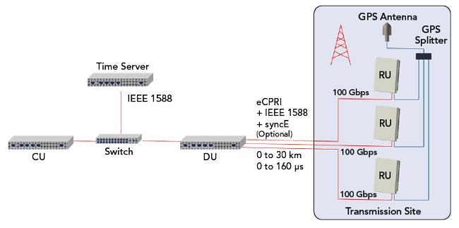
Figure 4 System using GPS at the RU.
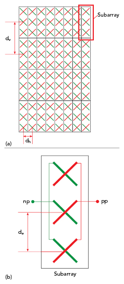
Figure 5 Typical mMIMO antenna: full array (a) and subarray (b).
In some cases, cross-licensing agreements allow operators to use the spectrum of another operator to offer a joint service. This is referred to as multi-operator RAN (MORAN). From the O-RU perspective, two fundamental sharing architectures exist: If each operator uses its own O-DU, the O-RU must act as two independent RUs to the DU. If not, only the O-RU and the O-DU are shared between operators. MORAN is transparent to the RU. Such an architecture brings restrictions, such as time-division duplex (TDD) downlink and uplink transmission periods aligned over both operators’ networks, which must be carefully handled to avoid conflicts.
RADIO ARCHITECTURE FOR mMIMO
The O-RAN fronthaul interface supports both conventional radios, with two or four transceivers, or mMIMO radios. MIMO is a means to increase the capacity of a mobile network by using the spatial domain, where the “multiple input, multiple output” refers to the radio channel. Signals sent by multiple transmitters are received by multiple receivers. Assuming propagation conditions permit, advanced channel coding methods and signal processing algorithms enable separating the transmit signals from the receive signals. mMIMO applies when the number of single antenna terminals (i.e., number of users) transmitting at a given frequency and time is much less than the number of base station antennas receiving. TDD, reference sequences and feedback from the terminals to the base station help apply the same principles to the downlink.
In general, the more transceivers in a mMIMO system, the more users can be served over the same communication channel, assuming the propagation characteristics support user discrimination. The 3GPP standards provide up to 256 transceivers. However, as the cost and power consumption increase with the number of transceivers, practical configurations for a mMIMO base station range between 16 transmitters and 16 receivers (16T16R) and 64 transmitters and 64 receivers (64T64R).
The antennas in a mMIMO system are arranged in an array, where each antenna may consist of a subarray of antenna elements. A typical arrangement for a 64T64R panel is shown in Figure 5, a 12 × 8 antenna array (see Figure 5a) comprising 32 polarized subarrays. Each subarray is made of six antenna elements, where three antenna elements radiate with a negative polarization, indicated by “np,” and the other three antenna elements with a positive polarization, indicated by “pp” (see Figure 5b).
With conventional, passive base station antennas, antenna gain is an important factor. The antenna gain is defined as the ratio between the maximum radiated power at a specific angle and the power radiated by a hypothetical antenna transmitting the same total power isotropically, i.e., equally distributed over the full sphere. It is assumed that the hypothetical antenna radiates all the power without any loss between its antenna port and free space. For the same power at the antenna feed, the radiated power of a directional antenna at boresight will be greater than the corresponding isotropic antenna by the gain factor.
To enable comparison with conventional radio architectures, which have a remote radio head and a separate passive antenna, the 3GPP has defined a reference radio architecture for mMIMO. This reference architecture defines two reference points for conducted and radiated measurements,5 assuming a transceiver unit array connected to a composite antenna (see Figure 6). The transceiver unit array contains the transmitters and receivers, generates the modulated transmit signals and performs receiver combining and demodulation. The composite antenna consists of the radio distribution network and the antenna array, the interface between the transceiver unit array and the composite antenna is called the transceiver array boundary (TAB). The two points of reference defined by 3GPP are the TAB for conducted measurements and the far-field region for radiated measurements, also referred to as over-the-air measurements.
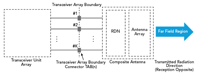
Figure 6 AAS radiated and conducted points of reference. Source: 3GPP.5
The RF output power of the transmitter limits both data rates and coverage. The output power typically refers to the power combined from all transceivers, which is the conducted power measured at the TAB. The corresponding measurement of radiated power is called the effective isotropic radiated power (EIRP), which includes the gain of the composite antenna. For example, a radio panel that provides 200 W (53 dBm) of RF power at the TAB and feeds an antenna array with 25 dBi gain at boresight will have an overall power measured at boresight of 78 dBm EIRP.
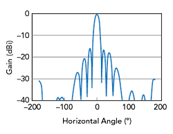
Figure 7 Typical azimuth antenna pattern for a user beam at 0°.
From antenna array theory, the far-field antenna array pattern of a linear array is the product of the single element pattern and the array factor (AF), assuming all antenna elements are the same kind, point in the same direction and are excited with equal power. The AF is the far-field radiation pattern of an array of isotropic radiators. Provided no coupling occurs between radiating elements, a linear array with 12 rows and eight columns and an element spacing of half-wavelength (λ/2) will have an AF of 96 (i.e., 19.8 dB). Coupling between the elements will reduce the AF and minimizing coupling can only be achieved by proper design; however, it becomes increasingly difficult when the element spacing de is less than a wavelength, particularly less than λ/2.
Sidelobes are another important characteristic of antenna arrays. The sidelobe level (SLL) is the maximum power from a sidelobe normalized by the strength of the main lobe. Alternatively, the inverse value, i.e., the ratio between the strength in the direction of the main lobe and the maximum sidelobe level, is often used and referred to as the sidelobe level suppression (SLS). In a mMIMO antenna, the actual beam pattern depends on the subarray radiation pattern and the amplitude and phase relationships between the subarrays, which are defined by the beamforming vector applied at the beamformer. The beamforming vector yielding the pattern with the lowest sidelobe levels typically uses different phase and amplitude values. For maximum output power, all the amplitudes need to be identical. To compare the radiation performance of different mMIMO active antenna units (AAU), only phase variations are allowed in the beamforming vector; the amplitudes are forced to be the same. To illustrate, Figure 7 shows a typical beam pattern with SLLs less than -16 dB.
O-RAN MMIMO ARCHITECTURES
The RU in a mMIMO AAU can be separated into its functions (see Figure 8). Some are only required once, while others, like the transceivers, are used multiple times. Each transceiver serves a single polarization of a radiation panel subarray. Among the functions used only once is the fronthaul interface connecting the O-RU to the O-DU, the beamformer, clock synchronization, management and control.
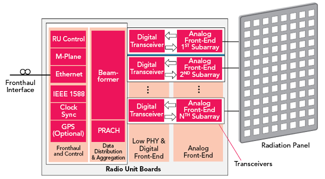
Figure 8 Typical RU architecture for a mMIMO AAU.
The fronthaul uses an Ethernet interface and is separated into the C-, U-, S- and M-planes. The M-plane interpreter and manager connects to the O-RU controller, which sets up and oversees the overall well-being of the unit. The O-RU controller measures the power consumption, temperature, output power and relative amplitude and phase accuracies for both receive (Rx) and transmit (Tx) to let the DU exploit channel reciprocities. It hosts multiple event counters and reports statistics, warnings and errors through the M-plane to either the O-DU or directly to the management system. The O-RAN ALLIANCE has standardized this as the service management and orchestration framework. S-plane packets following the IEEE 1588 PTP protocol are interpreted independently. PTP information is used to synchronize the O-RU clock to the network. As noted earlier, a built-in GPS receiver can be used as an alternative clock.
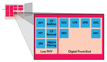
Figure 9 Elements of a digital transceiver.
The beamformer connects to NTx transmitters and NRx receivers. If NTx = NRx = N, which is usually the case, the beamformer is said to be connected to N transceivers, with all transceivers identical. Each transceiver consists of the digital transceiver and an analog front-end. For each layer, the beamformer performs two matrix multiplications for each subcarrier (SC). During transmit, the vector of resource blocks contained in each radio layer is multiplied by the Tx beamforming matrix to yield a vector of SCs for each transceiver. Likewise, during receive, each vector of SCs received from every transceiver is multiplied by the Rx beamformer to yield the SC vector for all layers. Figure 9 shows the functions of each digital transceiver, which contains the low PHY and digital front-end. The digital front-end encompasses front-end functions like filtering, gain settings and linearization in the digital domain, and the low PHY addresses time-frequency conversion and OFDM signal generation.
In the downlink direction, the SCs from the beamformer containing data in the frequency domain are transformed to the time domain within the iFFT. The OFDM signal is formed by adding a CP and passed to the digital front-end for digital up-conversion, comprising filtering, the frequency shift of the baseband signal and digital-to-analog conversion. For the downlink, the digital front-end includes crest factor reduction, which reduces the peak-to-average ratio of the OFDM signal, and digital predistortion (DPD), which linearizes the power amplifier. The uplink signals from the analog front-end are converted into the digital domain using analog-to-digital converters and digitally down-converted to baseband. With the down-converted signals, the CP is removed and the signal is converted to the frequency domain via the FFT. The OFDM symbols are then passed to the Rx beamformer. The low PHY also contains special functions for physical random access channel (PRACH) and sounding reference signal (SRS) filtering. The PRACH and SRS signals are passed to the fronthaul interface, and the O-DU post-processes the SRS and PRACH data.
The analog front-end (AFE) connects to the radiating panel and contains analog components like power amplifiers, filters, drivers and baluns and may contain switches and circulators. The AFE amplifies the Tx and Rx signals to and from the antennas. It must provide sufficient dynamic range for the Rx and Tx paths, isolate the paths and manage any noise introduced by the power amplifier stages. The radiating panel is designed to provide the required gain for the mMIMO system and the horizontal and vertical steering.
SUMMARY
This article has provided a tutorial on the architecture of the O-RAN and the approach to standardizing the interfaces between the RU, DU and CU to achieve interoperability and provide an environment for new entrants and network innovation. mMIMO is one RAN implementation to improve data capacity in areas with high mobile traffic, and the article discussed the functional architecture of a mMIMO RAN meeting O-RAN specifications.
A future article will discuss the mMIMO architecture and performance parameters of the RU, applying the concepts to the design of two AAUs: for the North American band from 3.7 to 3.98 GHz and the European band from 3.3 to 3.8 GHz.
- O-RAN ALLIANCE, web: www.o-ran.org/.
- 3GPP, RAN3 Technical Report TR38.803v1.1.0, Section 11, Figure 11.1.1-1, www.3gpp.org/ftp//Specs/archive/38_series/38.801/38801-100.zip
- O-RAN Fronthaul Working Group, “Control, User and Synchronization Plane Specification,” O-RAN, WG4.CUS.0-v05.00.
- O-RAN Fronthaul Working Group, “Management Plane Specification,” O-RAN, WG4.MP.0-v05.00.
- 3GPP, TS 37.145-1 V16.5.0 (2020-12), “3rd Generation Partnership Project; Technical Specification Group Radio Access Network; Active Antenna System (AAS) Base Station (BS) Conformance Testing; Part 1: Conducted Conformance Testing (Release 16),” Chapter 4, 3GPP, December 2020.
References