

A MIMO antenna operates at 2.45 and 5.8 GHz. Two decoupling methods are designed to improve isolation. For the 2.45 GHz frequency band, odd-even mode analysis is used to improve isolation through impedance matching. S12 is reduced by 9 dB. For the 5.8 GHz frequency band, an E-shaped defected ground structure reduces S12 by 13 dB without affecting the lower frequency band.
The use of MIMO antenna technology greatly improves channel capacity and transmission efficiency of a communication system without increasing working bandwidth and power. To meet miniaturization requirements, however, the distance between antenna elements is reduced, and coupling between ports is inevitable. Several approaches have been proposed to improve isolation between MIMO antenna elements. Some adjust the position and distance between ports.1 Incorporating decoupling structures with metamaterials is also relatively common.2,3,4,5,6,7 The isolation of some antennas is improved by introducing single-ended lines or parasitic structures.8,9,10,11,12,13,14 Defected ground structures are also employed.10,15,16,17,18 The use of resonant cavity decoupling structures and other structures has been reported as well.19,20,21,22
Current decoupling schemes are based mainly on structures that achieve high isolation through continuous adjustment and optimization. The work described here starts from the theory, considering that the odd-even mode analysis method is suitable for matrix decoupling, so it can be applied to MIMO antenna design. The odd-even mode analysis method is often used in the design of radio frequency circuits.23,24 The calculation process is simplified by separate analysis and calculation of the odd and even modes. It is commonly used in the design of microwave structures such as filters, waveguides, metamaterials and antennas.25,26,27,28,29,30 This greatly simplifies design of the decoupling structure at 2.45 GHz and avoids tedious optimization and simulation.
By comparing the influence of different structures on the antenna, an “E” shaped defected ground structure is selected to improve isolation at 5.8 GHz. This improves isolation in the 5.8 GHz frequency band without affecting the 2.45 GHz frequency band.
ANALYSIS
The odd-even mode analysis method is widely used in the analysis of symmetrical networks such as the Wilkinson power divider and directional coupler. It adopts the idea of symmetry and asymmetry, which decomposes the single-signal excitation into odd mode excitation and even mode excitation and uses the superposition theorem to greatly simplify the analysis. For MIMO antennas with commonly used symmetrical structures, the odd-even mode analysis method is applicable.
The two-port MIMO antenna is regarded as a two-port network, as shown Figure 1.
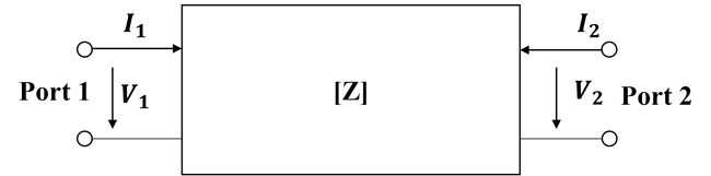
Figure 1 Two-port network model.
The impedance matrix of the two-port network is
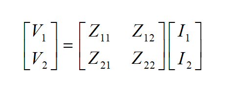
The signal excitation of the network is divided into odd mode excitation and even mode excitation.
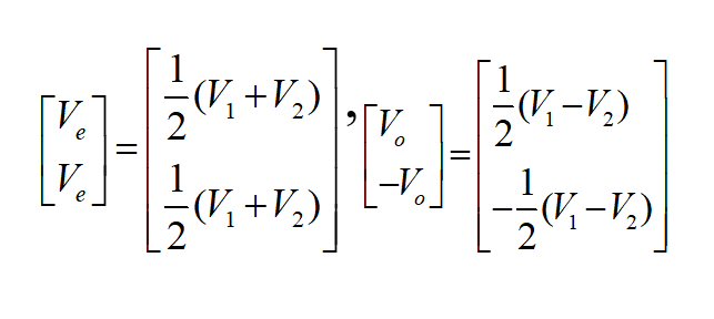
Where 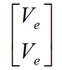 is the two-port even mode excitation,
 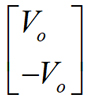 is the two-port odd mode excitation.
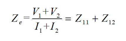
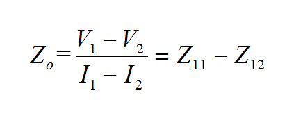
Due to network reciprocity and symmetry conditions, Z12 = Z21 and Z11 = Z22. The odd mode impedance and even mode impedance are obtained as follows:
According to the relation between Z and S matrices,
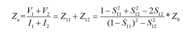
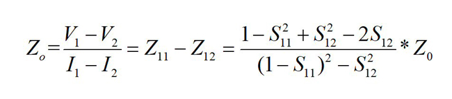
If the antenna is well matched and isolation is high, then S11 = S22 = 0 and S12 = S21 =0. Substituting these values into the above formula, Ze = Zo = Z0 is obtained. When Ze = Zo = Z0, it is also easy to obtain S11 = S22 = 0 and S12 = S21 = 0. Therefore, by adding a suitable decoupling network, the odd mode impedance and even mode impedance of the network are respectively equal to the characteristic impedance, which simultaneously improves isolation and matching characteristics.
ANTENNA DESIGN AND SIMULATION
The MIMO antenna unit is based on a planar inverted F antenna element (see Figure 2). By bending the planar inverted F antenna element, its size is reduced while forming resonant frequencies at 2.45 and 5.8 GHz. Moreover, loading of the short-circuit via also changes the position of the antenna zero voltage, thereby further reducing antenna size. The antenna is built on an FR4 substrate with a loss tangent of 0.02 and a dielectric constant of 4.4. The substrate is 42.5 × 52 × 1.6 mm, and the ground plane is 35 × 52 mm. Other dimensions are listed in Table 1. Figure 2a is the uncoupled antenna with simulated S-parameters shown in Figure 3a. It matches well at both 2.45 and 5.8 GHz; however, the distance between the two antennas is only 0.128 λ, so it is necessary to design a decoupling structure to improve isolation.
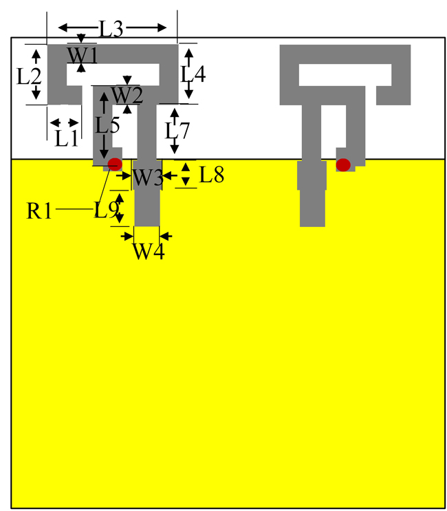
Figure 2a Uncoupled antennas.
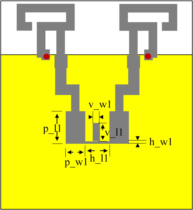
Figure 2b Antennas with T-type decoupling network.
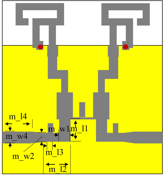
Figure 2c Front view with defected ground structure.
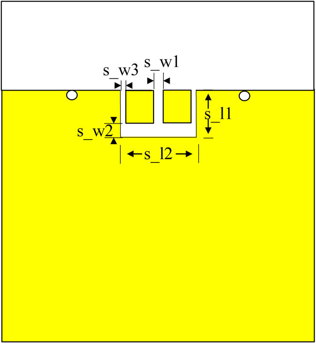
Figure 2d Back view with defected ground structure.
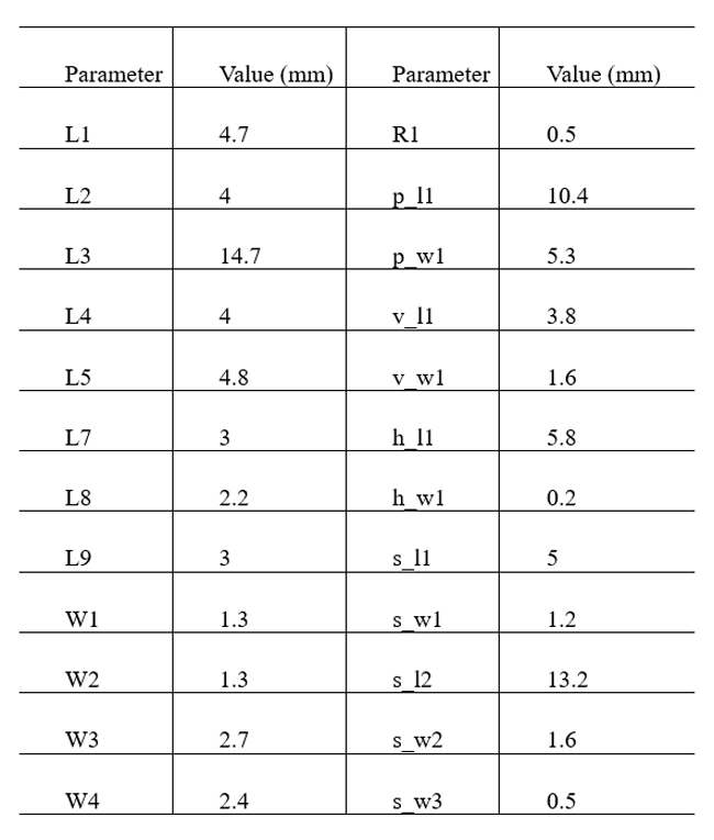
Table 1 Antenna dimensions