
A new microstrip branch-line coupler with compact size and wideband harmonic suppression uses modified radial stub loaded resonators. The new structure not only reduces the occupied area to 14.8 percent of a conventional branch-line coupler at 580 MHz, it also has high eleventh harmonic suppression. A fractional bandwidth greater than 5.2 percent is achieved while the phase difference between S21 and S31 is within 90 ± 1.0 degrees. The measured fractional bandwidths of |S21| and |S31| within 3 ± 0.5 dB are 24.1 and 24.2 percent, respectively, while insertion loss is comparable to that of a conventional branch-line coupler.
Branch-line couplers are widely used in microwave applications such as mixers, power amplifiers and frequency multipliers. They have two drawbacks: first, because the conventional branch-line coupler is composed of four quarter-wavelength (λ/4) transmission line sections at the designed frequency, it occupies a large area, especially at low frequencies. Second, the conventional design has harmonics at integral multiples of the fundamental operating frequency.
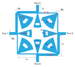
Figure 1 Branch-line coupler layout.
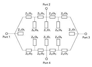
Figure 2 Branch-line coupler equivalent circuit.
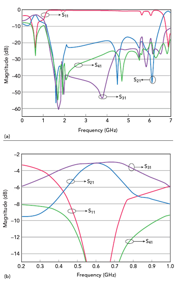
Figure 3 Simulated |Sxx| from DC to 7.0 GHz (a) and 0.2 to 1.0 GHz (b).
Much work has been reported in recent years to achieve both a compact design and harmonic suppression.1-16 Usually, there are two methods, the first is to load the coupler with shunt open stubs. With shunt open stubs inside the free area of the branch-line coupler, Eccleston and Onga4 reported a size reduction of 37 percent compared to a conventional design at 1.8 GHz. Based on a similar idea, Mondal and Chakrabarty5 described a branch-line coupler with a 42 percent size reduction at 2.4 GHz, including fifth harmonic suppression. The second design method is to introduce slow-wave resonators in the coupler structure. Using compensated spiral compact microstrip resonant cells, Gu and Sun6 described a branch-line coupler with its area reduced to 24 percent of a conventional design with second and third harmonic suppression at 2.4 GHz. However, the isolation was not ideal. By introducing high-low impedance resonators inside the free area of the coupler, Wang et al.7 proposed a slow-wave branch-line coupler with its area reduced to 28 percent of a conventional design at 2.0 GHz, but with only second harmonic suppression. While other methods8-16 achieved compact size, they need improvement to suppress harmonics.
In this work, a new microstrip branch-line coupler with compact size and wideband harmonic suppression is described. It uses modified radial stub loaded resonators based on our previous work.17 A 580 MHz branch-line coupler was designed, fabricated and measured. It reduced the occupied area to 14.8 percent of a conventional design at the same frequency and also has high eleventh harmonic suppression. Its fractional bandwidth is greater than 5.2 percent, while the phase difference between S21 and S31 is within 90 ± 1.0 degree.
CIRCUIT DESIGN
The topology of the design comprises eight modified radial stubs loaded inside the free area of a conventional branch-line coupler (see Figures 1 and 2). Each stub is composed of a short high impedance line and a long, radial, low impedance line. The length of the high impedance line is very short, less than λ/10, where λ is the guided wavelength at the operating frequency.
Each high impedance line can be considered a lumped element with a negligibly small value, and its inductance effect on the main transmission lines between two adjacent ports can be ignored. The capacitance caused by the low impedance lines is distributed in parallel with the main transmission lines. This increases the per unit length capacitance of the main transmission lines between two adjacent ports. An increased propagation constant means a shorter physical structure can be used to yield the required electrical length compared with a conventional transmission line. This new type of slow-wave loading does not increase the circuit area, as the periodic slow-wave loading is located inside the branch-line coupler. A desired slow-wave factor is achieved by properly adjusting the structure parameters. When the electrical length of the loaded high-low impedance resonator is an odd multiple of λ/4, where λ is the guided wavelength at the spurious resonance frequency, harmonic signals that occur at the integral multiples of the fundamental are suppressed.
After optimization using full-wave electromagnetic simulation software, the final parameters of the branch-line coupler are: W0 = 1.70 mm, W1 = 1.56 mm, W2 = 0.57 mm, L0 = 5.0 mm, L1 = 13.7 mm, L2 = 12.1 mm, R01 = 10.5 mm, R02 = 8.0 mm, R03 = 6.0 mm, R04 = 10.0 mm, R05 = 8.5 mm, R06 = 7.0 mm, θ01 = 60 degrees, θ02 = 30 degrees, θ03 = 30 degrees and θ03 = 18 degrees. These dimensions can be easily implemented with standard printed circuit board etching processes. The substrate used has a relative dielectric constant of 2.94, a thickness of 0.76 mm and the total area of the branch-line coupler is 590.2 mm2.
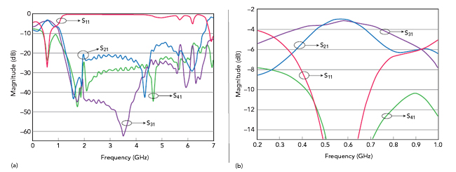
Figure 4 Measured |Sxx| from DC to 7.0 GHz (a) and 0.2 to 1.0 GHz (b).