
Intermodal oscillation of multimode InGaAs/InP lasers at X-Band frequencies are stabilized using self-forced oscillation of self-injection-locked, triple-phase-locked loop (SILTPLL), self-mode-locking (SML) and a combination of SML and SILTPLL. As the number of SML modes are increased, lower phase noise close to the carrier is measured. With 201 modes with intermodal oscillation frequency of 10 GHz, a phase noise of -157 dBc/Hz at 10 kHz offset from a 10 GHz carrier is predicted, while any random phase error among self-mode-locked modes can be corrected using a self-forced oscillation technique. A compact realization is feasible using a heterogeneously integrated InP multimode laser (MML) on Si photonics, using low loss SiN resonators as delay elements and SiGe low noise RF electronics.
Low phase noise RF sources are important elements of coherent detection in many RF applications, such as terrestrial and space communications. One of the key technological challenges faced by efficient front-end electronics for reconfigurable wireless communication, sensitive electronic warfare, jamming resistant radar and diversified remote sensing systems is reliance on highly stabilized local oscillator frequency sources. The traditional method of generating stable RF signals by multiplying the frequency of a highly stable crystal oscillator1 suffers from high power consumption, large size, poor AM noise and high AM-to-PM noise conversion, compared with forced oscillation techniques such as injection locking and phase-locked loops.2 Alternatively, an optoelectronic oscillator has been developed and reported for X- and K-Band with a frequency resolution better than 50 kHz and phase noise better than -130 dBc/Hz at 10 kHz offset from the carrier.3–5 A single chip design minimizes the environmental impact of temperature, vibration and radiation that influences long-term frequency stability. A small IC is preferred over its commercial 19 in. rack-mountable frequency synthesizer counterpart because of its smaller size, weight, power consumption and lower cost.
This article describes a compact chip-level integration using the intermodal output of a multimode semiconductor laser in the tens of GHz. While its performance using different frequency stabilization methods is reported elsewhere,6-8 its salient points are reviewed here to provide an overview of the single chip design.
MML AS AN RF SOURCE
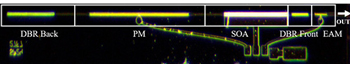
Figure 1 Fabricated DBR-based multi-mode, multi-section, semiconductor laser on a 0.8 mm x 4.6 mm InP chip.
A distributed Bragg reflector (DBR) multimode, multi-section semiconductor laser for RF generation is shown in Figure 1. It has no external reference and uses optical components fabricated with an InP process from the SmartPhotonics foundry.9 The device has four major sections: semiconductor optical amplifier (SOA) for gain, phase modulator (PM) for RF frequency tuning, filtering DBR for lasing function at select wavelengths, and electro-absorption modulator (EAM) for mode number control using multi-quantum well InGaAs/InP for multi-mode laser (MML) operation at 1550 nm with intermodal RF signal of tens of GHz. The lengths of the DBR back and front mirrors are 600 and 200 μm, respectively, the phase section length is 1250 μm and the SOA length is 800 μm. To form the complete laser cavity, the sections are connected by shallow-etched waveguide. The total cavity length, including the connecting waveguide of approximately 4,000 μm, yields an intermodal oscillation frequency of about 11.5 GHz for multiple modes over the 80 GHz gain spectrum of the SOA. The external EAM, 200 μm long, is used to selectively suppress various modes. Electrical connections are placed on the chip to provide DC bias for the operation control of SOA, PM and EAM. A via connects the ground pad to the backside of the chip.
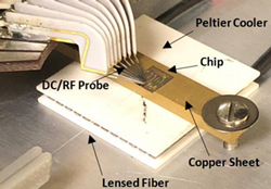
Figure 2 DBR-based multi-mode multi- section semiconductor laser test environment.
The microchip is mounted on a temperature-controlled surface (see Figure 2) for static and dynamic characterization of MML in a constant temperature. A copper sheet placed under the microchip and mounted on a Peltier cooler maintains 20°C throughout testing, using a thermistor and temperature controller maintaining the fluctuation to ±0.2°C. Mechanical probe stations provide electrical microprobes for the DC and RF input and the optical lensed fiber holder to collect the optical output. The optical output is monitored with an optical spectrum analyzer (OSA) through the lensed fiber optical coupler and photodiode. Its dynamic modulation has an important role in the phase-locking process of RF signals with greater than 50 MHz bandwidth. Intermodal oscillations are detected using an external high speed photodetector and displayed on an RF phase noise analyzer.
The EAM section controls the laser modes by shifting the quantum-confined Stark absorption edge. PM and EAM bias were initially set at 0 V, and the measured test of the integrated laser showed five dominant modes on the OSA. The fundamental mode was around -12 dBm at 1550.85 nm when the SOA injection current was 80 mA. The mode gap between each mode was around 11.5 GHz, which correlates with the estimated effective cavity length of 13.065 mm. The free-running intermodal output was around 11.5 GHz with about -10.6 dBm power at 11.5496 GHz. Poor phase noise of -5 dBc/Hz at 1 kHz offset from the carrier and -30 dBc/Hz at 10 kHz offset was recorded, as well as a 30 MHz center frequency shift over 10 minutes. Timing jitter was estimated to be 266.1 ps for 1 kHz to 1 MHz offset frequencies, before significant reduction using self-forced oscillation techniques.
The intermodal RF is tuned when a DC injection voltage is applied to the PM section (shown in Figure 1). An applied bias from -5.0 to 0 V to the PM section changes the index of refraction in the optical waveguide and the effective laser cavity length, causing a shift in the intermodal oscillation frequency. The phase section tuning sensitivity was measured at several PM biases; greater than 700 MHz tuning at X-Band was achieved with an average frequency tuning sensitivity of approximately 150 MHz/V. Compared to other techniques, this tuning range and sensitivity performance is among the best reported since its tuning sensitivity is significantly better than that of conventional RF voltage-controlled oscillators (VCOs).10
Novel forced oscillation techniques of self-injection locking11 (SIL) and self-phase-locking loops12 (SPLL) were used to improve the stability of the intermodal oscillation frequency. An optimized delay line using self-injection locked triple phase-lock loop (SILTPLL)13 improves the phase noise performance without any external reference.
MML SILPLL STABILIZATION
To improve the stability of the free-running oscillation frequency, forced oscillation was employed. When a stable source is available, frequency stabilization using an external frequency reference has been reported by Daryoush et al.14 However, self-forced oscillation techniques are useful when constructing a clean frequency source2 as an external reference to stabilize distributed oscillators.15
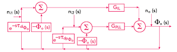
Figure 3 Control theory representation of a SILPLL16 composed of a SIL11 with time delay of τdi and a SPLL12 with time delay of τdp.
Referring to Figure 3, the conceptual block diagram of a self-injection-locked phase-locked loop (SILPLL)11 using a control theory representation is shown by the injection locking loop with the GIL path. A portion of the oscillator output signal is delayed by a long delay (τd) and fed back to the oscillator with coupling factor ρ. The phase of the delayed signal is compared to the instantaneous phase of the current signal to generate an error signal for self-injection. The phase noise of the self-injection locking system at offset angular frequency of ωm is expressed by equation (1):11

In equation 1, Sni and Sn0 are the residual noise of the system and the phase noise of the oscillator, respectively. When the gain of the feedback system is suffice, the phase noise introduced by the free-running oscillator is to be significantly reduced.