
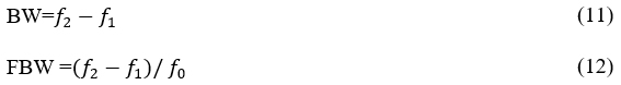
Regardless of the configuration and the equivalent model, it is always possible to reduce it to an RLC circuit in series or in parallel, like any microstrip line.14
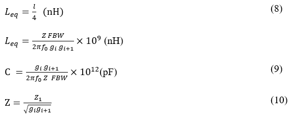
with
Where gi are the Chebyshev lowpass prototype filter element values, Z1 is the line impedance (50 Ω) and n is the number of resonators
FILTER DESIGN
This work considers the design of a third order Chebyshev broad bandpass filter with a center frequency ƒ0 = 15.8 GHz and a 3.3 GHz BW (for a 20.9 percent FBW). The chosen waveguide has a rectangular section (15 mm×7.5 mm), with fc10= 10 GHz (see Figure 4). The symmetrical inductive iris (see Figure 2) is designed and optimized using HFSS and CST. The final filter dimensions are listed in Table I.
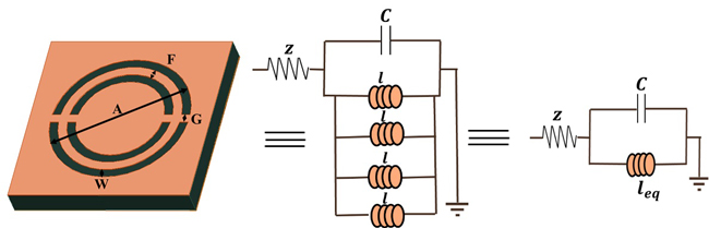
Figure 4 Three section waveguide filter.
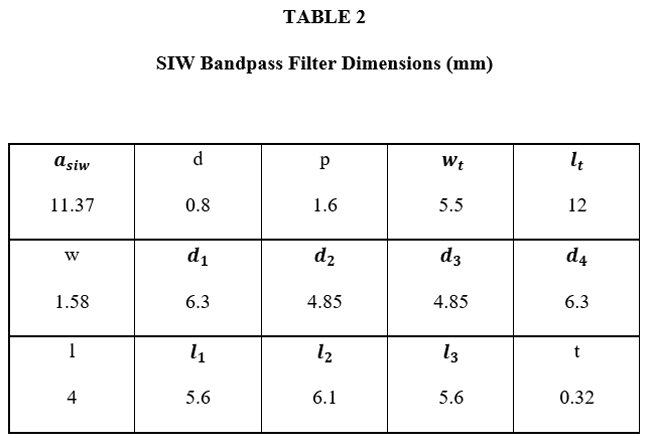
The SIW structure with symmetric irises (see Figure 5) uses Rogers Duroid 5880 with a permittivity εr= 2.2, loss tangent tan (δ)= 0.0009 and height hsiw= 0.51 mm. This substrate is chosen for its low loss tangent and common use in high frequency broadband applications.15 As with the waveguide filter, design and optimization is done using HFSS and CST. The final filter dimensions are listed in Table II.

Figure 5 SIW three section bandpass filter design with symmetrical iris.
Before designing the multi-section SIW metamaterial filter, a single cell is simulated in ADS (see Figure 6). Using the parameters and equations previously cited, the following values are used:
gi= [1 0.9786 1.1391 0.9786 1]
C= 0.9439 pF
leq= 0.1074 nH
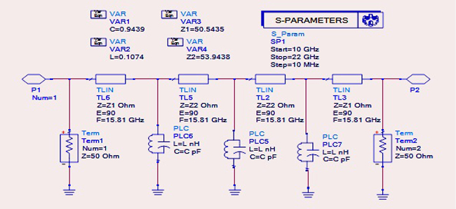
Figure 6 Bandpass filter ADS model.
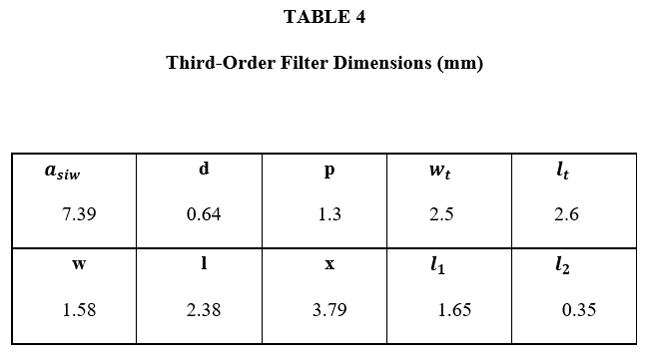
Resonator dimensions are listed in Table III. The three-section filter design is shown in Figure 7 with final dimensions listed in Table IV. The dimensions for each filter cell are the same.
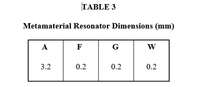
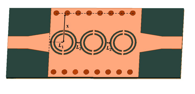
Figure 7 Three resonator SIW structure.
SIMULATION AND MEASUREMENTS
Figure 8a is the simulated frequency response of the waveguide filter. In-band return loss for the HFSS and CST models is greater than 23 dB and for ADS it is greater than 20 dB. Insertion loss is .02 dB. There are two waves of ripples, and three peaks, corresponding to the third order. The S parameters of the SIW structure (see Figure 8b) show an in-band return loss of greater than 19 dB for both HFSS or CST models, and an insertion loss of about 2.4 dB.
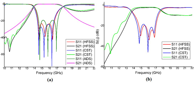
Figure 8 Modeled frequency response of the waveguide bandpass filter (a) and SIW bandpass filter with symmetric irises (b).
The dimensions in Table III are used for the design and simulation of one metamaterial resonator in HFSS (see Figure 9). It is clear from Figure 9a that the permittivity is negative throughout the frequency band. The permeability varies, but when it is negative, the refractive index n becomes negative. This causes a resonance at 19.4 GHz.
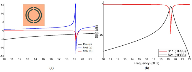
Figure 9 Metamaterial resonator permittivity, permeability and refractive index (a), and frequency response (b).