
The effect of interference from Wi-Fi on the BT speaker was evaluated inside a multi-story residential building using Altair’s wireless propagation and radio network planning software, WinProp.8 For accurate analysis, the residential building model was detailed, comprising the multi-story design with thick walls, flooring, staircase, fireplace, cabinets, doors, windows and roof (see Figure 12). The BT speaker was placed in one corner of the living room and the Wi-Fi router in the corner of an adjacent room (see Figure 12b). The speaker was assumed to use the latest BT5 technology11 and the Wi-Fi router the 802.11n standard.12
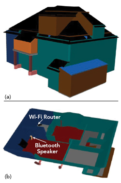
Figure 12 Multi-story house (a) and cross-section (b) showing the locations of the router and BT speaker.
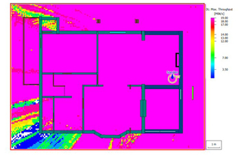
Figure 13 Maximum achievable DL throughput for the BT speaker.
The BT speaker has near omnidirectional coverage along the horizon, as shown in Figure 11a. BT is a packet-based protocol with a master/slave architecture, one master can communicate with up to seven slaves in a piconet. For this CDMA-based technology, the maximum number of codes available for a user on one carrier is seven. As BT supports a maximum data rate of 3 Mbps for the uplink (UL) and downlink (DL) through the enhanced data rate transmission mode, the maximum achievable throughput should be 21 Mbps. Due to non-ideal orthogonality among the codes, however, the maximum achievable DL throughput is 19 Mbps (see Figure 13).
As 802.11n supports MIMO systems, a router with two antennas was used for the analysis, where each antenna carries one data stream in a 2 × 2 MIMO scenario. The router antennas are well matched for the 2.4 GHz Wi-Fi bands (see Figure 14a). For MIMO, the antennas must be well matched at the carrier frequency and well isolated to avoid interstream interference. Figure 14a shows the two antennas have good isolation, approximately ∼25 dB. A better indication of independent behavior is the envelope correlation coefficient (ECC), shown in Figure 14b. For MIMO applications, an ECC value of 0.5 is considered okay, higher than 0.5 is considered bad and 0.3 or less is good. Being an orthogonal frequency-division multiplexing technology, 802.11n uses time-division duplex separation. The maximum achievable throughput is, therefore, the maximum achievable data rate. Figure 15 shows the Wi-Fi access point in the modeled location provides good coverage for most of the house.
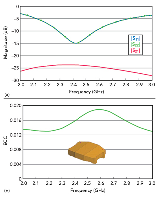
Figure 14 Wi-Fi router antenna matching and isolation (a) and ECC (b).
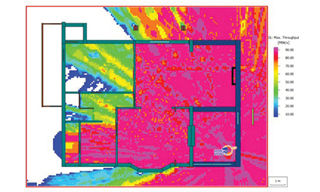
Figure 15 Maximum achievable Wi-Fi throughput using 802.11n, showing good coverage throughout most of the house.
The Wi-Fi router operates on a 2412 MHz carrier, with the BT at 2442 MHz. The two are close to each other both in frequency and physically in the house. This leads to a decrease in BT throughput due to leakage from Wi-Fi into the BT frequency band, especially in the areas close to the Wi-Fi router (see Figure 16a). The interference from Wi-Fi to BT can be mitigated with additional filtering in the BT module. When the leakage from Wi-Fi causing the interference is attenuated by an additional 20 dB, the throughput is improved, as shown in Figure 16b.
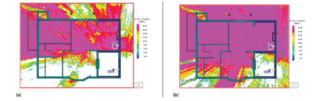
Figure 16 Effect of Wi-Fi interference on BT throughput: The white area near the Wi-Fi router indicates little BT coverage (a). Coverage can be improved with filtering to attenuate Wi-Fi leakage (b).
CONCLUSION
Simulation-driven virtual prototyping used during a smart product’s development will reduce development time and ensure the design qualities of the product. These techniques were illustrated in three development stages of a wireless speaker: 1) PCB layout, 2) antenna design and integration and 3) wireless coverage and interference evaluation. Simulation-driven virtual prototyping results in smart products that are more cost-effective and provide higher quality and reliability.
References
- “5G Innovations for New Business Opportunities,” 5G-PPP, https://5g-ppp.eu/wp-content/uploads/2017/01/5GPPP-brochure-MWC17.pdf.
- U. Sellgren, Simulation-Driven Design – Motives, Means and Opportunities, Doctoral Thesis, The Royal Institute of Technology, 1999.
- S. Koziel, X. S. Yang and Q. J. Zhang, Simulation-Driven Design Optimization and Modeling for Microwave Engineering, Imperial College Press, London, 2013.
- G. G. Wang, “Definition and Review of Virtual Prototyping,” ASME Journal of Computing and Information Science in Engineering, Vol. 2, No. 3, September 2002, pp. 232-236.
- Altair PollEx, www.altair.com/pollex/.
- “Universal Serial Bus Specification Revision 2.0,” April 2000, http://sdpha2.ucsd.edu/Lab_Equip_Manuals/usb_20.pdf.
- J. Rashed and C. T. Tai, “A New Class of Resonant Antennas,” IEEE Transactions on Antennas and Propagation, Vol. 39, September 1991, pp. 1428-1430.
- Altair Feko, www.altair.com/feko/.
- S. R. Best and J. D. Morrow, “Limitations of Inductive Circuit Model Representations of Meander Line Antennas,” IEEE Antennas and Propagation Society International Symposium, June 2003.
- U. Wetzker, I. Splitt, M. Zimmerling, C. A. Boano and K. Römer, “Troubleshooting Wireless Coexistence Problems in the Industrial Internet of Things,” IEEE International Conference on Computational Science and Engineering, August 2016.
- “Bluetooth Core Specification Version 5.0 Overview,” Bluetooth SIG, www.bluetooth.com/bluetooth-resources/bluetooth-5-go-faster-go-further/.
- “IEEE 802.11n-2009 – IEEE Standard for Information technology--Local and Metropolitan Area Networks--Specific requirements--Part 11: Wireless LAN Medium Access Control (MAC) and Physical Layer (PHY) Specifications Amendment 5: Enhancements for Higher Throughput,” IEEE Standards Association, October 2009, https://standards.ieee.org/standard/802_11n-2009.html.