
It seems like 5G is just starting, so why talk about 6G? Because cellular technologies take more than a decade to go from vision to deployment. Take 5G as an example. Work on the technology started well before the first specification emerged in 2018, as the International Telecommunication Union (ITU) started developing the vision for 5G in 2012. Each new generation of cellular technology represents a step-function increase in complexity. 5G leverages new spectrum for commercial mobile communications, among other new concepts. With consumers and businesses accustomed to getting new capabilities with each generation, 6G needs to deliver much higher performance than 5G. Early 6G targets in key performance indicators represent a 10x to 100x increase over 5G. The 6G vision, ITU’s “Network 2030,” includes peak data rates to 1 Tbps, lowering latency to 0.1 ms and increasing density to 10 units/m2.
Delivering 6G in time while meeting consumer expectations for never-before-seen, sci-fi-like capabilities requires the industry to increase research on 6G. Several universities are running research programs to advance 6G: The University of Oulu in Finland launched the first 6G program, 6G Flagship, in May 2018; the University of Surrey in England launched the 6G Innovation Centre in November 2020. The Wireless Internet of Things Institute at Northeastern University in the U.S. is also working on 6G technology; it hosted a virtual event on 6G in October 2020, with plans to repeat it annually. Also, many countries have started to invest in 6G. In November 2020, China launched a satellite to test the Earth-to-space radio channel for frequency bands above 100 GHz, which are above the mmWave 5G bands (i.e., FR2). In the U.S., the Next G Alliance launched in October 2020 with the mission to advance North American leadership in 6G. Japan recently announced investments of almost $500 million for 6G research.
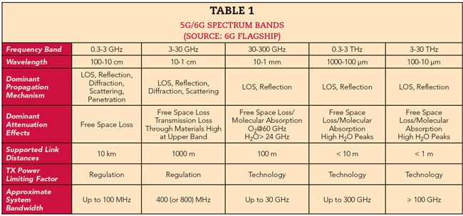
6G will bring new and exciting use cases beyond those introduced with 5G. One area of focus is to combine sensing, imaging and precise timing with mobility and leverage artificial intelligence to create innovative applications. Some of these will require wider bandwidths - thus, the move from mmWave to sub-THz frequencies (see Table 1). Studying sub-THz frequencies is critical to advance 6G development. Among other aspects, researchers need to determine the error vector magnitude (EVM) performance while using these frequency bands and higher modulation bandwidths.
MEASUREMENT CHALLENGES
With sub-THz systems, good EVM performance is critical to achieve higher-order modulation for high data throughput. To avoid masking the device being tested, the test system must also deliver better EVM performance, which requires a low signal-to-noise ratio (SNR). While maximizing signal power helps increase the SNR, reducing the signal power is necessary to avoid compressing the components along the signal chain. The noise contributions to SNR can also be problematic for wideband applications because the noise power is integrated over the wider signal bandwidths.
Phase noise is another issue to contend with. Up- and down-converting between the IF and sub-THz frequencies requires a local oscillator signal source and frequency converter. Frequency multipliers are often used in the local oscillator (LO) path rather than the signal path to avoid impacting the signal modulation characteristics. However, frequency multipliers increase the phase noise and can introduce additive phase noise, further degrading the multiplied LO phase noise.
Impairments provide additional challenges. While filters can remove the undesired image products, LO feedthrough, out-of-band spurious and other undesired artifacts from nonlinear mixing, these components can introduce linear amplitude and phase errors over the wide signal bandwidths. Adaptive equalization in the receiver of a wide bandwidth test system can remove linear amplitude and phase impairments across the signal bandwidth. However, the adaptive equalizer only addresses linear amplitude and phase error; it cannot remove any nonlinear impairments from compressed amplifiers in the test system signal path nor LO phase noise. Noise and nonlinear impairments will remain and degrade the residual EVM of the test system.
The test system requires flexibility to handle candidate waveforms for 6G, since the physical layer standards are not yet defined. Including design simulation will aid the evaluation of system performance under various simulated scenarios.
SUB-THZ MEASUREMENTS
Figure 1 shows an example testbed meeting the performance demands of 6G research. The transmit chain includes a multichannel arbitrary waveform generator (AWG) to generate wide bandwidth modulated IF signals, a signal generator to provide a low phase noise LO for the up-converter and an up-converter to convert the IF signal from the AWG to a sub-THz frequency. The receive chain includes a down-converter to convert the sub-THz signal back to IF using the same signal generator LO and a multichannel, high performance oscilloscope to digitize it. Software is used to generate and analyze 6G candidate waveforms.
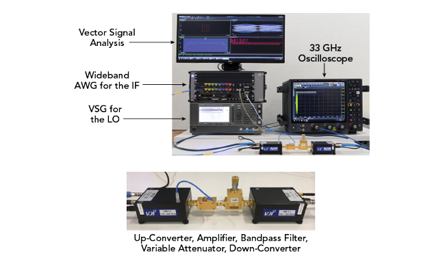
Figure 1 Sub-THz testbed.
Using this setup, single carrier, quadrature amplitude modulation measurements were performed using varying modulation bandwidths. Because 6G waveforms are not defined, preliminary 802.11ay test software was used for signal generation and analysis, as 802.11ay is an emerging wideband standard with optional bandwidths similar to those planned for 6G. Figure 2a shows the performance of a two-channel bonded (CB2) signal centered at 144 GHz and a channel bandwidth of 4.32 GHz, using D-Band (i.e., 140 to 170 GHz) up/down-converters (left) and G-Band (i.e., 140 to 220 GHz) up/down-converters (right). Figure 2b shows a four-channel bonded (CB4) signal centered at 144 GHz and a channel bandwidth of 8.64 GHz, using the same D- and G-Band up/down-converters. The modulation bandwidth shown in Figure 2b is double that of Figure 2a, which increases the integrated noise power within the signal bandwidth. There is also greater linear amplitude and phase variation as the signal bandwidth is increased. These factors degrade the EVM performance, which goes from approximately 2.1 to 3.4 percent using the D-Band converters and from 2.2 to 3.5 percent using the G-Band converters.
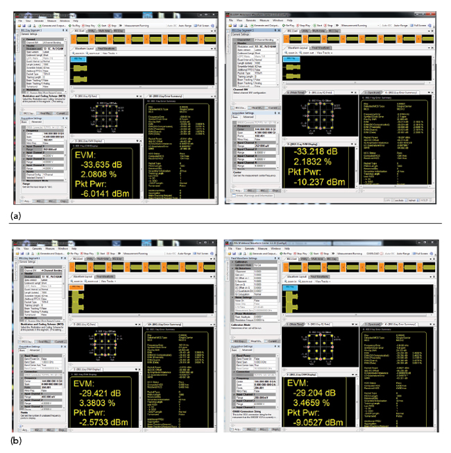
Figure 2 144 GHz, 802.11ay CB2 (a) and CB4 (b) measurements using D-Band (left) and G-Band (right) up- and down-converters.
The same test setup can perform measurements for “extreme” bandwidth cases, such as an occupied bandwidth of 10 GHz (see Figure 3). With a conducted test, the baseband waveform is pre-corrected before being downloaded into the AWG and the adaptive equalizer is disabled. The resulting EVM is 4.7 percent. Repeating the test over-the-air (OTA), the baseband waveform is pre-corrected for the channel and signal path before being downloaded to the AWG. In this case, the adaptive equalizer is enabled to compensate for OTA channel impairments. The OTA EVM performance degrades slightly, increasing from 4.71 to 4.75 percent.

Figure 3 Performance of a 16 QAM, 10 GHz occupied bandwidth signal at 144 GHz in a conducted test setup (a). OTA setup (b). Both conducted and OTA tests used the G-Band up/down-converters.
INNOVATION AND FLEXIBILITY
6G will further integrate communications technologies into society and human life, bringing mixed reality experiences and telepresence, while playing an important role helping move to global sustainability, a better society and increasing productivity across industries. Like its predecessors, 6G comes with new challenges, particularly the wider bandwidths and higher frequencies to support new use cases. To develop the potential of 6G, researchers need test solutions with better EVM performance, so the test system does not mask the true performance of devices and systems.