
For many years switch filter banks have been designed as custom RF assemblies with long lead-time, large NRE charges and extreme custom packaging and specifications. A new modular approach to switch filter bank design has been introduced that provides the design engineer with the opportunity to maintain a custom design with filter topologies, and utilize standard existing low profile packaging and switching along with a high level of RF performance.
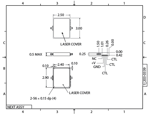
The mechanical configuration starts out with a low profile housing that is 3.0 L x 2.5 W x 0.50 inches tall excluding SMA-female field replaceable connectors. A mechanical outline of the modular switch filter bank is shown in Figure 1 . The housing is machined out of aluminum to maintain a lightweight package that can be laser-welded for a leak proof seal. The main housing consists of seven individual channels that can be removed for easy assembly and tested prior to installation in the main housing. The removable channel housings allow this filter bank to be utilized as a two-channel up through a seven-channel configuration without any modifications to the main housing. The removable channels allow the design engineer to test and align each individual filter and verify electrical performance prior to bank installation. The 0.50" max height also makes this unit extremely attractive in applications where VME cards may be utilized. Standard finish on the modular switch bank is silver plate with other finishes available at no increase in cost. There are 2-56 tapped holes provided on the bottom surface for mounting.
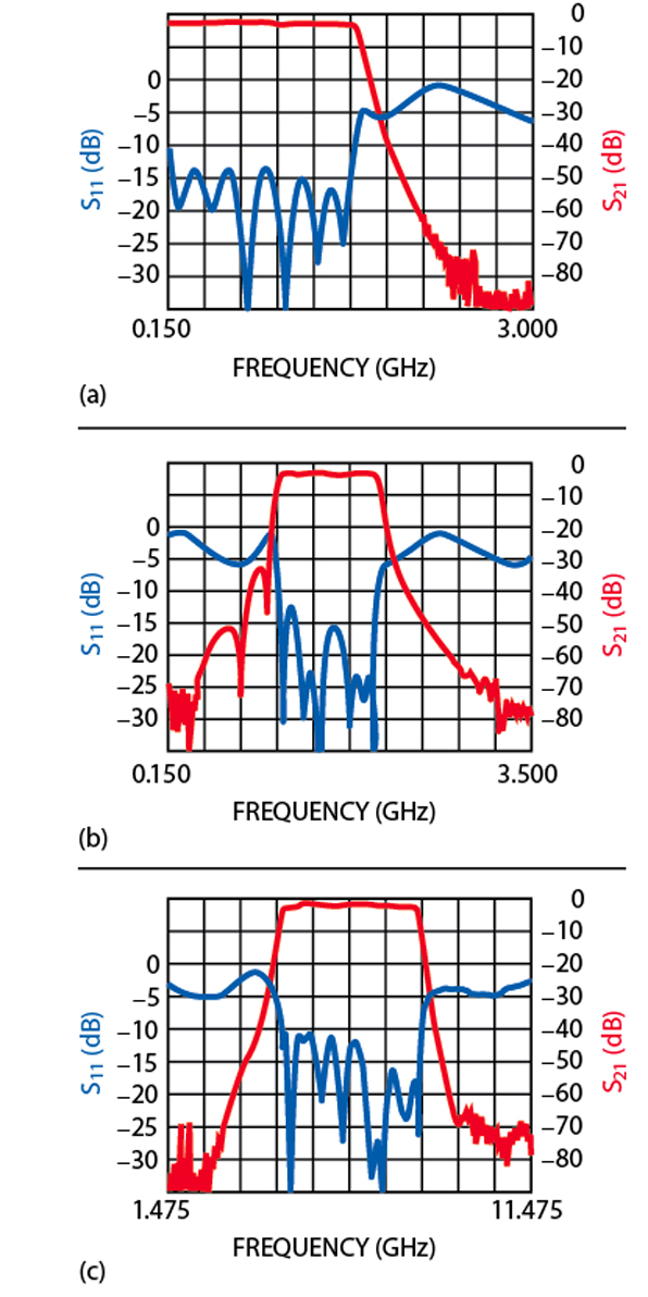
The RF configuration is by far the strong suite of this design. This unit is capable of working from 100 MHz to 10 GHz. With the use of improved broadband coils, this switch filter bank is able to work across a broad frequency range in various configurations (bandpass, low pass and high pass) with no sacrifice in performance. Figure 2 shows channel one as a low pass filter that has a passband from 100 to 1500 MHz. Channels two through seven are bandpass filters that cover 950 to 8300 MHz in various band splits. Filter topologies include Chebyshev, Gaussian, Butterworth, linear phase and elliptical. Maximum SWR on this unit is 2.0 to maintain minimum tune and test time. Insertion loss on all channels is 5.0 dB typical with all channels amplitude matched to ±1 dB across the passband. Stopband requirements vary based upon the requirements. As selectivity becomes more critical on modern designs switch isolation becomes very important. Standard isolation on the modular bank is specified as 60 dB minimum. Typical amplitude ripple is specified as ±0.5 dB with 0.5 dB as the norm. As can be seen, maximum design flexibility is provided with limited impact on time and cost.
The digital control circuitry has been designed with standard TTL logic. The configuration has been established to allow two-bit or three-bit logic control depending on the number of channels. A 54LS145 driver is used to select the required digital code. Installation of one jumper wire allows the flexibility of the two bits versus three bits. The digital circuitry has been designed to provide a standard switching speed of < 400 ns. This number will vary slightly depending on the number of filter poles and topologies. There are three control pins that are 0.030" in diameter to allow wiring harness installation with no pin breakage in assembly. A standard +5 V power supply is used with a current draw of 100 mA. The use of one power supply allows design engineers easy installation and configuration in board layout.
The new modular switch filter bank has been designed for military and industrial grade applications. All high grade COTS or Mil. Spec. parts have been used in the design. The unit meets all standard MIL-STD-202 environmental requirements such as gross leak, random vibration, sine vibration, thermal shock and a standard operating temperature of -40° to +85°C. The modular bank has been designed to be a high performance unit with a reasonable price and delivery. Typical applications for this product are receiver designs, synthesizers, radars and guidance systems.
Conclusion
A compact modular switch filter bank is now available that provides two through seven channel operation with high isolation, low insertion loss and low passband ripple. The new assembly is digitally controlled using two- or three-bit logic and operates from a single 5 V DC supply. The unit features high performance custom filter designs using various topologies in a standard, low profile package at low cost.
K&L Microwave Inc., Salisbury, MD (410) 749-2424, www.klmicrowave.com. Circle No. 302