
A reliability study of a blind mate 1.85 mm coaxial interconnect for automated test equipment (ATE) mmWave applications achieves the design target of 20,000 insertions with a significant margin.
The adoption of mmWave frequencies for consumer applications such as 5G has created several new challenges for the ATE industry. One is the need for a reliable blind mate interconnection between the printed circuit board (PCB) test fixture and ATE measurement instrumentation. For package testing, the device under test (DUT) resides in a socket located on the PCB test fixture. In the case of wafer probing, a probe head is used instead of a DUT socket, and the probe head connects to the die in the silicon wafer being tested. Figure 1 shows a commercial ATE system for mmWave testing.1 An ATE system requires multiple types of interconnects for the different electrical signals (e.g., power, digital, RF, mmWave). The ATE must automatically mate to the PCB test fixture without any kind of manual interaction, such as threading connectors. Another requirement is the reliability of the interconnect; for ATE applications, the interconnect needs to support 20,000 insertions while guaranteeing ATE system specifications.
Figure 2 shows an ATE system interface with the different types of interconnects to the PCB test fixture. Spring pin interconnects are the dominant type for power and digital. RF and mmWave signals require coaxial interconnects, due mainly to the isolation requirements, not just the frequency range. Apart from reliability, an important point regarding the development of interconnect technologies for ATE applications is the frequent use of custom designs. Although ATE test cells are operated in manufacturing environments with controlled temperature and humidity, some applications are tested at cold and hot temperatures, from -20°C to +120°C. These high and low temperatures are applied to the DUT or a small region around the DUT, while the ATE interconnect interface operates, in the case of hot testing, at a much lower temperature. It is important to ensure that in the worst-case scenario, the interconnect remains within its specified temperature range.
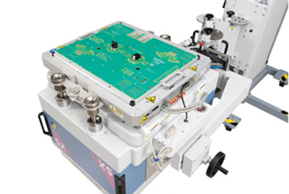
Figure 1 Advantest V93000 ATE system with dual site mmWave fixture for package testing.
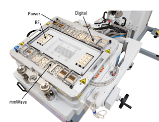
Figure 2 Top side showing the digital, power, RF and mmWave interconnects.
Figure 3 shows the bottom side of a mmWave ATE test fixture and the different mating interconnects. For the spring pin-based interconnect, a plated via connects to the spring pin tip and to a PCB signal trace, which is then routed to the DUT. For the RF and mmWave signals, a coaxial mating connector is used. In the figure, a coaxial cable from the coaxial interconnect in the test fixture connecting to another connector close to the DUT socket is visible. The choice of this connector is the responsibility of the test engineer. The reason for using a coaxial cable and not a PCB signal trace: the cable provides flexibility with the layout and, more importantly, significantly lower loss, since even a thin coaxial cable is less lossy than the best PCB signal trace.1 Since loss is critical for RF and mmWave applications, it is important to minimize the PCB signal trace lengths.

Figure 3 Bottom side showing the mating connectors and signal routing.
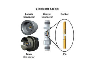
Figure 4 Blind mated, spring-loaded 1.85 mm interconnect
1.85 mm INTERCONNECT DESIGN
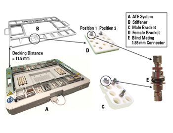
Figure 5 Connector integration on the ATE system and test fixture.
Rosas et al.2 developed a 1.85 mm blind mating interconnect design (see Figure 4). The requirement is mode-free operation to 70 GHz with no interconnect failure for 20,000 docking cycles, which is fully compliant with ATE specifications. This frequency range supports both 5G and WiGig applications. Note the IEEE 287 standard3 compliant 1.85 mm female interface on the non-mating side of the interconnect, which supports using off-the-shelf 1.85 mm cable assemblies to connect the blind mating interface to the ATE measurement instrumentation and to the connector in the PCB test fixture close to the DUT. The test fixture, for example, could use a 1.85 mm male to mini-SMP coaxial cable assembly. The 20,000 docking cycle requirement is based on the use case for ATE systems, which are used around the clock for high volume semiconductor production. A debug/characterization scenario for the ATE test cell might consist of 10 dock/undock cycles of the ATE test fixture in one day; however, in production, the test fixture might be docked to the ATE system for several days without being undocked.
Figure 5 shows how the 1.85 mm blind mating connector pairs are implemented on the ATE system and DUT test fixture sides. A maximum of 64 mmWave interconnects are supported, with the exact number depending on the ATE system configuration. The connector interface is spring-loaded on the male, ATE interface side and designed to self-align as the interface is mated. The mating action is part of the test fixture docking process to the ATE system. The ATE interconnect interface (see Figure 2) is composed of several interconnects apart from the 1.85 mm blind mate connectors, which require a large docking force and, in turn, require special care with the mechanical design of the entire docking interface. The 1.85 mm blind mate interconnect is not a “push-on” type connector, which would never support the performance requirements. This blind mating interconnect requires a constant specific pressure on the entire mating surface to achieve the required 70 GHz frequency bandwidth. If this pressure is not correct or homogenous, effects like in-band resonances will appear in the interconnect frequency response.
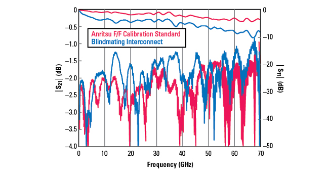
Figure 6 Interconnect performance compared to Anritsu 70 GHz female-female calibration standard.
The 1.85 mm connector standard offers many advantages for the blind mate interface. The long length of mechanical engagement of the adapter housing properly aligns the interface before electrical connection, protecting the center conductor. The long length at the housing end also acts as an electromagnetic interference shield to improve isolation. In addition, a large surface area at the reference plane helps ensure 360 degrees of ground, which reduces resonances. The plating meets the requirements of MIL-PRF-39012, in accordance with MIL-DTL-45204, for use in the military and space industries. This means the plating is composed of thick hard gold over a thick layer of nickel. The quality of the plating makes it durable enough for the 20,000 cycle requirement and able to survive the 60,000 cycles performed in reliability testing.
Figure 6 shows the measured performance of the blind mate interconnect integrated in the ATE system. To better evaluate the measured data and provide a reference measurement for comparison, the same setup of vector network analyzer (VNA) and cables was used to measure a female-to-female adapter from the Anritsu 1.85 mm calibration kit (Anritsu 3654D), which is rated to 70 GHz. Although the measured performance satisfies the ATE interconnect requirement for mmWave applications, the challenge is to guarantee this performance across 20,000 mating cycles, the target lifetime of the interconnect. Note that this reliability requirement is significantly higher than the specification defined in the IEEE 287 standard for the 1.85 mm threaded connector, which is 5,000 cycles.3