
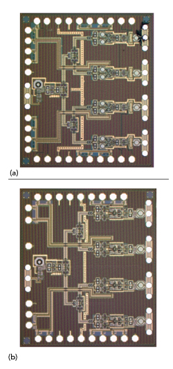
Figure 6 Tx IC (a) and Rx IC (b), each with four channels.
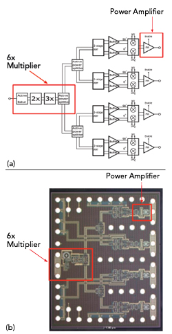
Figure 7 Four-channel Tx block diagram (a) and IC layout (b).
AWR Microwave Office circuit design software was used with the AWR AXIEM® electromagnetic (EM) simulator to design the Tx and Rx ICs from the transistor level, using the IHP SG13S SiGe process design kit (PDK) available for AWR software. The SG13S 130 nm SiGe bipolar CMOS process for mmWave applications has high speed HBTs with fT = 240 GHz and fmax = 330 GHz.
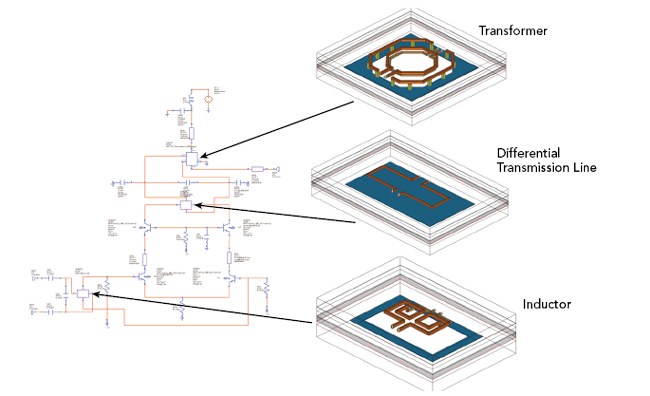
Figure 8 PA schematic with transformer, differential transmission line and inductor layouts.
A block diagram of the four-channel Tx RFIC and the actual Tx die are shown in Figure 7. The active balun, 6x harmonic multiplier chain (2x and 3x multipliers cascaded) and one of element’s PAs are highlighted to show their locations on the RFIC. Three active power dividers split the signal among four symmetric lines, each feeding a two-stage polyphase filter that generates 90 degree phase shifted I and Q LO signals. The power dividers are followed by the buffer amplifier, I/Q modulator and PA stages. A schematic of the PA, developed using components from the foundry PDK for Microwave Office, is shown in Figure 8, highlighting the transformer, differential transmission line and inductor. These passive structures are electrically large compared to the wavelength and required EM analysis and optimization using the AXIEM solver. The EM components were embedded as subcircuits in the schematic for co-simulation with Microwave Office. By including EM analysis combined with the PDK models of the chip-level amplifier yields excellent agreement between the measured performance and the simulation (see Figure 9).
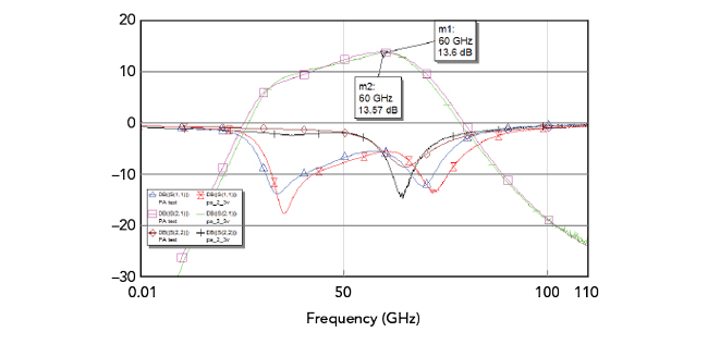
Figure 9 Simulated vs. measured PA gain, |S11| and |S22|.
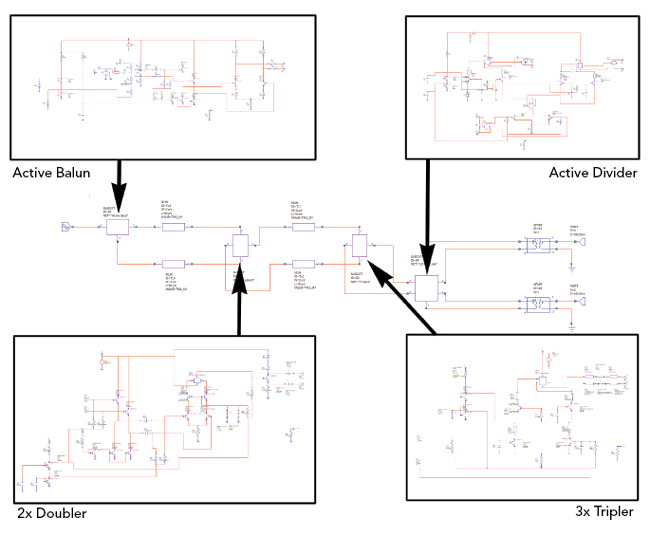
Figure 10 6x multiplier schematic.
Simulations of the active balun, harmonic multiplier chain and active power divider on the output (see Figure 10) were performed assuming a 10 GHz input and 2.4 V bias. The simulation results shown in Figure 11 provide useful insight into the operation of the multiplier, enabling an understanding of the power levels of the spurious signals being generated. From a radar design perspective, it is beneficial to have this information to suppress these spurious signals, warranting the additional design steps to fine-tune the circuit.
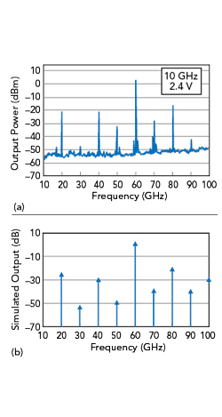
Figure 11 Measured (a) and simulated (b) output of the 6x multiplier.
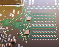
Figure 12 PCB with eight Rx channels using two Rx ICs.
MIMO Radar Measurement Results
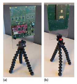
Figure 13 Back (a) and front (b) views of the radar system PCB.
The RF section of the receiver (see Figure 12) shows eight Rx channels supported by two Rx RFICs flip-chip mounted on a PCB. The front and back of the high speed signal processing back-end, mounted on a stand for lab testing, are shown in Figure 13. The phases and amplitudes of the receivers are calibrated with a single-point target measurement. Phase and amplitude correction factors are determined so the point target measurement provides an image of a point target at the correct angle.
“People flow” measurements of the 2D MIMO radar verified it can detect multiple people at the same time with 100 to 200 FPS (see Figure 14). The demonstrated range resolution was 3 to 5 cm, and the angular resolution was 3.5 degrees. During image formation, the Hamming windowing function was applied in the range direction and a -25 dB sidelobe level Taylor window was applied in the azimuth direction. The Taylor windowing function slightly degraded the angular resolution but reduced the sidelobe level, enabling the image to be formed with a higher dynamic range. The targets were well separated in the generated image.
Accurate phase measurement is useful when measuring very small movements of a target - using the displacement of the chest to determine the heartbeat and breathing rate of a human, for example. Frequency multiplexing has an advantage over time multiplexing for measuring, since all the channels were measured at the same time. This is seen in the radar multi-person heart rate variability (HRV) extraction, shown in Figure 15. Vital signs such as heart rate, HRV and breathing can be observed from the radar signal.
CONCLUSION
The design of a novel 60 GHz MIMO FMCW FDM radar for commercial applications has been described. The system provides high frame-rate measurement, excellent phase stability and a large FoV.The unique architecture and RFICs were designed so the system can be scaled to much larger radars while maintaining phase coherence among the channels. Both 2D and 3D imaging systems have been demonstrated and, to the best of the authors’ knowledge, this is the first 3D imaging, mmWave, frequency-division MIMO system of its kind.
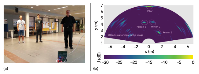
Figure 14 Three people in the radar field of view (a) and resulting image (b).
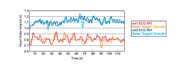
Figure 15 Results of multi-person HR and HRV extraction.
References
- J. Hasch, E. Topak, R. Schnabel, T. Zwick, R. Weigel and C. Waldschmidt, “Millimeter-wave Technology for Automotive Radar Sensors in the 77 GHz Frequency Band,” IEEE Transactions Microwave Theory and Techniques, Vol. 60, No. 3, March 2012, pp. 845–860.
- H. Forsten, T. Kiuru, M. Hirvonen, M. Varonen and M. Kaynak, “Scalable 60 GHz FMCW Frequency-Division Multiplexing MIMO Radar,” IEEE Transactions Microwave Theory and Techniques, Vol. 68, No. 7, July 2020, pp. 2845–2855.
- C. Pfeffer, R. Feger, C. Wagner and A. Stelzer, “FMCW MIMO Radar System for Frequency-Division Multiple TX-Beamforming,” IEEE Transactions Microwave Theory and Techniques, Vol. 61, No. 12, December 2013, pp. 4262–4274.