
Test applications that require microwave power from 1 to 18 GHz are usually addressed by two amplifiers, a solid-state unit to cover the low frequency range and a traveling-wave tube amplifier (TWTA) for the higher range.
The input signal must be switched between the two amplifiers and, if there is a common load, the output signal must also be switched. Depending on the nature of the test, this manipulation of RF cables is either done manually or automatically via an external GPIB (IEEE-488) compatible coaxial switching matrix and associated cables. The manual approach is very painstaking and can lead to system errors and repeatability problems due to repetitive attachment and removal of the precision high frequency RF connectors. The automatic approach corrects these problems, but there are a few issues to consider. First, the cost of the system must increase to account for the additional hardware. Secondly, the user must specify the external hardware and method used to accomplish the required system integration. A further concern involves external components that could prove to be awkward or inconvenient for the application.
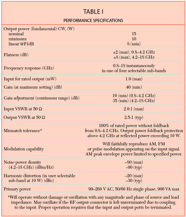
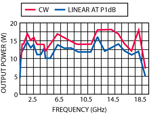
The model 10ST1G18 broadband microwave amplifier provides a cost-effective solution to these problems by combining solid-state and TWT amplifiers, along with all the associated switching hardware in one convenient bench-top instrument. System variables such as cable loss and coaxial switch insertion loss have been accounted for. The new amplifier is a totally self-contained, forced air cooled, broadband hybrid solid-state and TWT microwave amplifier designed for applications where low harmonic content is required in sub-band ranges, and high gain and moderate output power are needed. This reliable amplifier system provides a conservative 10 W minimum power output with low harmonic content. Figure 1 shows the amplifier's typical power output vs. frequency. Table 1 lists the unit's performance specifications.
The amplifier's front panel digital display shows forward and reflected output plus extensive system status information accessed through a series of menus via soft keys. Status indicators include power-on, warm-up, standby, operate, faults, excess reflected power warning and remote operation. Standard features include a built-in IEEE-488 (GPIB) interface, 0 dBm input for rated output, gain control, RF output sample port, VSWR protection for the TWT only (not required for the solid-state unit), plus monitoring of the TWT helix current, cathode voltage, collector voltage, heater current, heater voltage, base-plate and cabinet temperature. The appropriate sub-band is user selected from either the front panel menu or the GPIB interface. Modular design of the RF assemblies and power supplies allow for easy access and repair. Use of switching mode power supplies results in significant weight reduction.
The standard model 10ST1G18 amplifier is supplied with a removable enclosure that measures 19.8" x 11.7" x 27.0" and weighs 55 kg. The unit may also be shipped without an outer cabinet or with the enclosure removed for rack mounting with slides and front handles installed. Self-contained fans provide forced air cooling with air entry and exit in the rear. All RF connectors are in the rear as well. The RF input and RF output sample ports are type N female connectors, while the RF output is a type TNC female.
Typical applications include a variety of electromagnetic compatibility immunity standards that have test requirements above 1 GHz, telecommunications testing and immunity testing to the rigorous Bellcore GR-1089 standard.
Conclusion
The model 10ST1G18 broadband microwave amplifier has been developed to address testing needs in the 800 MHz to 18 GHz frequency range. This broad range, along with the low levels of harmonic distortion, places this new amplifier in a class by itself.
Amplifier Research,
Souderton, PA (215) 723-8181.
Circle No. 302