
The phases of all eight elements must be aligned before processing signals from the antenna. To do so, the eight elements’ receivers are connected to a ZB8PD-362-S+ eight-way splitter. The input of the splitter is connected to the transmitter channel of one of the transceivers. After coarse phase synchronization, a manual fine alignment of the receiver channel phases is performed on each board, adding a fixed angle to each channel as required to align them. Knowing that the two LOs are at the same frequency, the four signals of the master board now lead or lag the four channels of the slave board by a constant phase, which is also evaluated and compensated manually. After this alignment, the power divider is removed and the antenna array is connected to the eight receivers using equal length cables. For applications where more channels are needed, in the case of massive MIMO, a clock distribution network can be used to synchronize the frequency and phase among all the boards.
TESTING
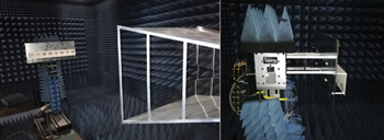
Figure 7 Monopole array and transceiver boards in the anechoic chamber.
To test the full system and validate the outcomes, real signals at various angles are recorded, beamforming weights are calculated on the fly and radiation patterns after post processing are recorded. Measurements are conducted in the controlled environment of an anechoic chamber using a Vivaldi transmit antenna, fed from the transmitter channel in the FMCOMMS5 master board (see Figure 7). The transmitter needs nine seconds to transmit one burst of data, so the motor that rotates the Vivaldi antenna is adjusted to an angular speed of 1/9 degree per second as it rotates from -90 to +90 degrees. The processing system captures data from the eight elements simultaneously at each step, accumulating data from the eight signals at 181 angles. The master and slave FMCOMMS5 boards are mounted on the opposite side of the receive antenna array, as shown in Figure 7. Before starting the measurements, phase calibration is performed as described.
The test mimics a UE signal transmitted toward a base station antenna array. Baseband data in LTE-A and 5G NR are modulated with quadrature amplitude modulation (QAM),13,14 so the test signal is quadrature phase shift keying (QPSK) modulated, with a length around 2,400 samples. At each stop angle, a burst of modulated QPSK data is sent through the Vivaldi antenna and received through the eight-element array. The receiver’s ADC sampling rate is set to 30 MSPS, with the channel bandwidth at 5 MHz. After recording data, beamforming weights are applied to the stored signals. In this test, the weights are calculated based on the linearly constrained minimum variance (LCMV) beamformer. An LCMV beamformer passes signals from preferred directions with maximum gain while blocking interference from other directions. The total output power after applying the LCMV weights is minimized under the constraints of source and interference directions.15 The steering capability of the array is limited to between -60 and +60 degrees for a total azimuth view angle of 120 degrees.
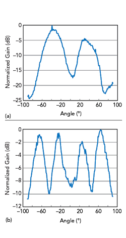
Figure 8 Normalized radiation patterns at 1.8 (a) and 2.6 (b) GHz, derived from the baseband signal after applying LCMV beamforming weights.
Several scenarios were tested, with two shown here: 1) The normalized radiation pattern with the source at 35 degrees and interferers at 10 and 65 degrees, operating at a carrier frequency of 1.8 GHz (see Figure 8a); 2) The normalized pattern at 2.6 GHz with two sources at 60 and 35 degrees and an interferer at 0 degrees (see Figure 8b).
CONCLUSION
An eight-element antenna array test bed for digital beamforming in LTE-A and 5G was developed and evaluated. The system, using commercial wideband transceivers covering the FR1 LTE-A and 5G NR bands, was tested in an anechoic chamber with an LCMV beamformer at 1.8 and at 2.6 GHz. The measurements agree with the predicted performance. This work will continue, using the system to evaluate DoA estimation algorithms for LTE-A and 5G base stations in noncontrolled environments.
ACKNOWLEDGMENT
This work is a collaboration between the Lebanese University and Universitat Politècnica de València and partially supported by the Lebanese University. It has been supported by a scholarship from Erasmus Mundus Welcome Program and by the Spanish Ministry of Economy and Competitiveness, under the project TEC2016-78028-C3-3-P.
References
- Ericsson, Ericsson Mobility Report, November 2019, www.ericsson.com/4acd7e/assets/local/mobility-report/documents/2019/emr-november-2019.pdf.
- A. Kuchar, M. Taferner, M. Tangemann and C. Hoek, “Field Trial With a GSM / DCS1800 Smart Antenna Base Station,” IEEE VTS 50th Vehicular Technology Conference, September 1999.
- “Overview of 3GPP Release 10,” Vol. 0.2.1, 3GPP, June 2014.
- “Services Provided by the Physical Layer, 3GPP TS 38.201 V15.0.0 Release 15,” 3GPP, July 2018.
- “3GPP TS 38.300 V15.2.0 Technical Specification 3rd Generation Partnership Project; NR and NG-RAN Overall Description,” 3GPP, June 2018.
- ”R4-1700199_NR Specific Beamforming New Requirements for NR,” 3GPP, January 2017.
- P. Zhou, “Target Networks in 5G Era Embracing Mobile Network 2020s,” Huawei, 2017.
- “TS 136 104 V10.2.0 Technical Specification LTE; Evolved Universal Terrestrial Radio Access (E-UTRA); Base Station (BS) Radio Transmission and Reception,” 3GPP, May 2011.
- “TS 38.101-1 V15.0.0 Technical Specification 3rd Generation Partnership Project; NR; User Equipment (UE) Radio Transmission and Reception,” 3GPP, July 2018.
- C. A. Balanis, “Antenna Theory: Analysis and Design,” Wiley, 2015.
- “CST Studio Suite 2017,” Dassault Systemes.
- “AD9361 Reference Manual,” Analog Devices.
- “TS 36.211 version 10.0.0 Release 10; Evolved Universal Terrestrial Radio Access (E-UTRA); Physical Channels and Modulation,” 3GPP, January 2011, p. 9.
- “3GPP TS 38.211 V15.2.0 Technical Specification 3rd Generation Partnership Project; NR; Physical Channels and Modulation (Release 15),” 3GPP, July 2018.
- B. D. Van Veen and K. M. Buckley, “Beamforming: a Versatile Approach to Spatial Filtering,” IEEE ASSP Magazine, Vol. 5, No. 2, April 1988, pp. 4–24.