
Product Features
A Modern Militarized Rubidium Frequency Standard
Datum Inc.
Beverly, MA
The last decade has seen widespread use of commercial-off-the-shelf (COTS) electronic equipment in military applications, allowing modern technology to be utilized quickly and less expensively. For the most part, this process has been successful provided that the commercial equipment is capable of reliable operation in the demanding MIL environment. To that end, a new rubidium frequency standard (RFS) has been developed that uses plastic encapsulated microcircuits (PEM), surface-mount devices (SMD) and other modern components to implement a replacement for the classic Efratom M-100 miniature military rubidium frequency standard.1
New features of the model 8130A RFS include high resolution digital tuning, numeric monitoring, internal temperature compensation and dual outputs. Provisions are made for low phase noise, special frequencies and +15 VDC power options. A condensed list of the product specifications for the 8130A is shown in Table 1 .2
|
Table 1 | |
|
Output frequency (MHz) |
5 to 10 (others as option) |
|
Output waveform |
Sine (squarewave as option) |
|
Output level (dBm) |
+7 nominal (each output) |
|
Harmonics (dBc) |
≤-40 |
|
Spurious (dBc) |
≤-80 |
|
Phase noise (dBc) |
(lower as option) |
|
Allan deviation |
≤ 1 x 10-11 t-1/2 for 1 ≤ t ≤ 100 sec |
|
Drift |
≤ 3 x 10-11 /month (after 1 month) |
|
Operating temperature range (°C) |
-40 to +68 |
|
Temperature sensitivity |
≤ 3 x 10⁻¹⁰ |
|
Supply voltage ( V DC) |
+22 to +32 (+15 as option) |
|
Power (W) |
≤30 (max) ≤12 (SS, +25°C) |
|
Warm-up time |
≤5 min to lock at +25°C |
|
Voltage sensitivity |
≤1 x 10-11 /10% |
|
Magnetic field sensitivity |
≤2 x 10-11 /Gauss |
Electrical and Mechanical Interface
The 8130A RFS's electrical and mechanical interface is similar to the M-100 unit that it replaces. Both are components that operate from 22 to 32 VDC unconditioned DC power and produce a high stability 5 or 10 MHz output. The new unit is smaller and lighter, has similar performance and capabilities, more features, and is about half the cost.
Fig. 1 Mechanical interface.
The 8130A mechanical interface is shown in Figure 1 . The unit is intended for mounting on its baseplate, which also serves as the thermal interface. The unit's electrical interface is implemented by a 15-pin male subminiature D power/control/monitor connector and two SMA receptacles for the RF outputs.
A block diagram of the 8130A is shown in Figure 2 . The unit is partitioned into a physics package, RF, servo, output and motherboard sections. As in all such units, a crystal oscillator produces an output that is locked to the Rb atomic resonance by a frequency lock servo. The physics package comprises lamp and cell ovens and the lamp exciter, and C-field, temperature controller and preamplifier circuits that support its operation. The servo section has a microcontroller driven fundamental and second harmonic synchronous detectors, a servo integrator and a lock detector. The RF section contains a 60 MHz voltage-controlled crystal oscillator (VCXO) and a 5.3125 MHz direct-digital synthesizer. The O/P section has dual RF output amplifiers, while the motherboard provides power conversion and filtering, and monitoring and control via an RS-232 interface.
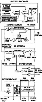
Fig. 2 Block diagram.
Physics Package
The main considerations governing the choice of the Rb physics package were a desire to maintain the high level of performance associated with a medium-size resonance cell operating at a moderate temperature, to leverage the company's proven integrated cell technology and to create a highly modular physics package design. The first consideration (maintaining a short-term stability of approximately 5 x 10-12 t-1/2 ) dictates a cell with a diameter and length of approximately 1" operating at about +80°C. The cell size then determines the dimensions of the microwave cavity and the rest of the physics package. The second consideration not only offers a ready source for the critical Rb lamps and cells, but also takes advantage of their significant heritage. The desire for a modular design led to including the lamp exciter, C-field source, lamp and cavity temperature controllers, and signal preamplifier within the physics package assembly, allowing the physics package to be operated as a testable sub-assembly. Other important physics package choices were to use active oven heaters and a step recovery diode (SRD) microwave multiplier. A transistor heater provides high efficiency but raises an issue of residual magnetic field that was solved elegantly in the LPRO design by making the microwave cavity from a high permeability material and wrapping the C-field coil directly around the resonance cell. Particular care is taken in the 8130A physics package to insure that the lamp and cell (cavity) ovens are rigidly connected so as to avoid relative motion under vibration. An improvement in signal-to-noise ratio (S/N) and short-term stability was made by including an optical filter in the light path to block spectral components from the Xe buffer gas in the Rb lamp. This also reduces the amount of vibrational modulation on the light. The VCXO is the only significant contributor toward the vibration sensitivity of the unit.
RF Chain
The 8130A RF chain closely follows the traditional architecture used in most of the Datum RFS products, 60 MHz and frequency modulated 5.3125 MHz drive to an SRD multiplier that generates an interrogation signal at the Rb-87 hyperfine resonance frequency as the difference between the 114th harmonic of 60 MHz (6840 MHz) and 5.3125 MHz at 6834.6875 MHz. A new feature of the 8130A is the use of a 32-bit direct-digital synthesizer (DDS) as the 5.3125 MHz source. Clocked at 20 MHz, the DDS provides a resolution of 3.41 x 10⁻¹³ by alternately stepping one of the two squarewave FM tuning words.
Servo Amplifier
Most rubidium frequency standards use a modulation rate that is comparable to the atomic linewidth, thus producing a recovered signal that contains a large second harmonic component. This relatively high modulation rate is desirable to support a wide servo bandwidth that best utilizes the high S/N and minimizes the stability requirements of the locked crystal oscillator. The second harmonic signal, while convenient as a means of lock detection, complicates the servo amplifier design by requiring a means to suppress it so as to not lose dynamic range for the fundamental discriminator signal. Several approaches have been used to attenuate the second harmonic signal including low pass filtration, notch filtration and frequency translation. The 8130A uses low pass filtration, but with a new implementation employing an eighth-order switched capacitor filter, which provides superior second harmonic rejection along with excellent phase stability.
Output Board
The standard RF O/P board contains output dividers and dual sine or squarewave output amplifiers. As an option, it includes a low phase noise 5 or 10 MHz oven-controlled VCXO (OCVCXO) and associated phase-locked loop (PLL).
Motherboard
Besides interconnecting the other boards, the motherboard contains circuits for power filtration and conversion, monitoring and control, and the RS-232 user interface. The standard configuration, which operates from +22 to +32 VDC, has a DC/DC converter to efficiently supply regulated +15 VDC to the electronic circuits. The physics package ovens operate directly from 22 to 32 VDC power via a separate power line. The other boards have local +12 and +5 VDC regulators. As an option, the entire unit can be operated from +15 VDC by simply eliminating the DC/DC converter, which is housed inside a shielded box on the motherboard. Extensive EMI filtration is provided by a shielded connector and on-board filter components. Monitoring functions are provided by an eight-channel, 12-bit data acquisition system (DAS) and a temperature sensor. A microcontroller implements the user interface via an RS-232 level converter.
Microcontroller Firmware
An enabling technology in the 8130A is the availability of small, inexpensive and complete single-chip microcontrollers (such as the programmable IC (PIC) devices from Microchip Technology). These devices and their associated firmware can be distributed throughout a design to replace discrete logic and enhance performance. The basic 8130A uses three PICs on its RF, servo and motherboards. The RF board device is mainly associated with the DDS synthesizer, handling the tuning and modulation functions. The servo board device generates reference signals to the switched capacitor filter and synchronous detectors, and handles lock acquisition and detection. The motherboard PIC is responsible for the user interface, internal communications, monitoring and temperature compensation. The FLASH memory and in-system programming (ISP) features of the PIC microcontrollers allow their firmware to be installed and updated after PCB assembly. The 8130A includes a 9600-baud RS-232 interface for control and monitoring purposes.
Parts Qualification and Screening
It is simply not practical to base a new RFS design on traditional MIL-spec parts that, if available at all, are too large, expensive and technologically obsolescent. Furthermore, PEMs and SMDs have been proven to be reliable when properly applied. Datum has therefore adopted a policy of using these devices strictly within their manufacturer's ratings and in homogeneous lots (reels, for example) after quality screening.
Mechanical Design
The mechanical design of the 8130A comprises the physics package, RF, servo, output and motherboards attached to a main bracket assembly that is mounted to a main L chassis having a slide-on cover. A flex circuit connects between the physics package and motherboard, and the SRD drive coax cable has an MMCX connector that mates with the RF board. The RF and servo boards plug into the motherboard, and the output board plugs directly into the RF board. There is essentially no hand wiring.
Windows Applet
A 32-bit Microsoft Windows® applet is available to facilitate communications with the 8130A via its RS-232 user interface. This program allows monitoring and control of the RFS, including frequency calibration and plotting of monitor signals.
Conclusion
This article has described a new generation of militarized rubidium frequency standards intended to replace the venerable M-100 unit. The 8130A utilizes modern microcircuits and surface-mount electronic packaging to provide enhanced functionality in a smaller size and at a lower cost while maintaining the ruggedness and environmental hardening required by tactical military applications.
Reference
1. Technical Manual TM OM/M-100, Model M-100 Rubidium Frequency Standard, Efratom Time & Frequency Products Inc., 1995.
Datum Inc., Beverly, MA (978) 927-8220.
Circle No. 302