


RFHIC Corporation has developed solid-state pulsed transmitters for C- and X-Band radar, providing 4 kW output power at C-Band and 5 kW at X-Band. The transmitters use RFHIC’s own GaN power devices in a redundant power amplifier (PA) architecture, which provides long lifetimes with “soft” failure. The systems are cooled using forced air.
C-BAND TRANSMITTER
The C-Band transmitter, model RRT54594K0-66, was designed for maritime, surveillance and weather radar applications between 5.4 and 5.9 GHz. The transmitter delivers a minimum of 4 kW peak pulsed power with 31 percent power consumption efficiency (see Figure 1). It handles pulse widths of 1 to 100 µs and up to 10 percent duty cycle, with typical pulse drop of 0.5 dB or less and rise and fall times less than 100 ns. The transmitter has excellent pulse fidelity, with pulse stability of 55 dB and spurious signals no greater than 40 dBc in the operating band. An input power of at least 15 dBm is sufficient to drive the transmitter to rated power.
The RRT54594K0-66 integrates four, 1.2 kW pulsed modules (RRP54591K2-42), which use RFHIC’s 240 W GaN on SiC transistors (IR56240NN). The GaN modules provide high power with high efficiency and an MTBF of approximately 80,000 to 100,000 hours. The transmitter is designed with an expandable hardware architecture, enabling users to add modules to achieve higher power without manually phase matching the modules.
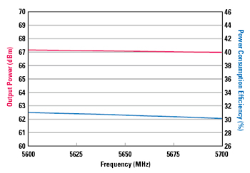
Figure 1 Output power and power consumption efficiency of the C-Band transmitter.
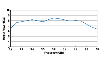
Figure 2 Output power vs. frequency of the X-Band transmitter with a 50 µs pulse at 10 percent duty cycle.
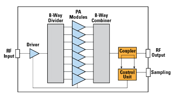
Figure 3 Redundant architecture of the X-Band transmitter. A similar approach is used with the C-Band transmitter, which integrates four PA modules.
The C-Band transmitter has embedded monitoring capabilities to detect abnormal system conditions, such as low power, excessive temperature, high voltage standing wave ratio (VSWR) or DC failure. An RS232 interface provides warning alarms or automatic shutdown to safeguard the system.
The RRT54594K0-66’s RF input connector is SMA, and the output is WR-159 waveguide, which has an insertion loss no greater than 0.2 dB and VSWR below 1.5:1. Weighing 88 lbs., the transmitter is packaged in a compact 47.4 cm x 42.1 cm x 25.1 cm “box,” which supports easy and stable installation on an antenna mast. The housing can be modified to fit in a standard 19 in. rack, an option if required by the application.
X-BAND TRANSMITTER
The X-Band pulsed transmitter, model RRT901005K0-57, was designed for radar applications operating between 9 and 10 GHz with an instantaneous bandwidth up to 500 MHz. The transmitter delivers at least 5 kW peak pulsed power (see Figure 2), with pulse widths to 100 μs and 10 percent duty cycle. Pulse droop is no greater than 1.0 dB, and pulse rise and fall times are less than 100 ns. Spurious signals are no greater than 60 dBc from 9 to 10 GHz. With 6 kW output power and 10 percent duty cycle, the power consumption is 4 kW maximum.
The transmitter combines eight, 800 W GaN PAs using RFHIC’s GaN on SiC transistors and achieves approximately 80,000 hour MTBF (see Figure 3). As with the C-Band transmitter, the RRT901005K0-57 is expandable. Users can add power modules to increase the output power without manually matching the phase of the new modules.
The transmitter has an RS-422 control interface to provide warning alarms and automatic shutdown to safeguard the system from damage. Should a PA module fail, the RRT901005K0-57’s control system will automatically identify and report it to the user through the upper management system. A liquid crystal display monitor on the front of the system shows the real-time status of operation, such as output power - with an accuracy of ±0.5 dB.
The RF input connector is SMA and the output has a WR-90 waveguide. The unit has a small form factor: 6 U x 19 in. for rack mounting, enabling straightforward system integration, and it weighs 117 lbs.
MODULAR DESIGN
With both the C- and X-Band transmitter designs, if one of the PAs fails, the output power drops by the power of the failed module. Unlike TWTAs or other tube amplifiers, the transmitters do not require full redundancy; even with multiple PA failures, the system gracefully degrades. Due to its scalable architecture, it allows the user to build higher power systems when needed.
RFHIC has an extensive PA portfolio to support customized design for unique customer requirements, from output power to frequency bands. RFHIC is the first and only commercial company whose portfolio spans GaN devices to systems. This high quality capability offers customers both off-the-shelf products and custom solutions, which help reduce capital expenses and shorten project development time.
RFHIC Corp.
Anyang, South Korea
www.rfhic.com