

Testing radar warning equipment in realistic scenarios is crucial to reliable performance in the field. Traditionally, dedicated instruments or test systems have been used for this. Now, commercial vector signal generators (VSG), such as the R&S®SMW200A from Rohde & Schwarz, offer an attractive alternative because of their increased bandwidth and processing power.
REALISTIC SCENARIOS
Modern VSGs can generate a realistic, dense RF environment, with the capability to play back a nearly unlimited range of signals from simple unmodulated pulses to radar signals with modulation on pulse (MOP). The high modulation bandwidth of these VSGs enables modern frequency-agile radars to be simulated. The signal source can be shared among different applications, from simple VSG to high-end radar simulation - all benefiting from outstanding RF performance. Using a single source for many applications reduces test and measurement costs and provides users with flexibility.
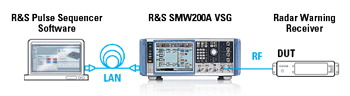
Figure 1 The R&S SMW200A VSG with R&S Pulse Sequencer PC software provides a compact, powerful radar simulator for the lab.
With the SMW200A VSG, Rohde & Schwarz offers a solution for testing radar warning equipment with realistic scenarios. Combining the generator with the PC-based R&S Pulse Sequencer software creates a powerful simulator with everything needed for testing (see Figure 1). The simulator can generate current and future radar signals, creating scenarios with multiple complex, high-resolution signals, and it can be used for all phases in the equipment lifecycle, from early design in the lab, integrated system testing in production, testing in the field and maintenance. The heart of the solution is the VSG, which supports all typical radar bands to 44 GHz. The flexibility of the digital hardware with 2 GHz internal I/Q bandwidth enables simulation of pulse-on-pulse scenarios with up to six overlapping pulses in an instrument with one RF port and a maximum pulse density of 6x 3.3 million pulses per second.
Radar warning receivers use input signals from multiple antennas to determine the direction of arrival of the signal from an emitter. This functionality can also be tested in the lab with coupled instruments that provide multiple synchronous signals.
SCENARIO EDITOR
In all stages of development, from initial functional testing to final operational simulation testing, engineers want realistic test cases reflecting what the radar warning receiver will see in operation. To support realistic simulation, the R&S Pulse Sequencer software can define a wide range of radar scenarios, from simple pulses to dense multi-emitter environments. As a standard feature, the software has smart pulse interleaving algorithms with an optimized, user-defined priority scheme. This feature enables lowest drop rates.
Alternatively, users can simulate actual pulse-on-pulse situations as they occur, without any pulse dropping. The user can configure all typical radar types: CW, frequency modulated continuous wave (FMCW) or pulsed, including wide bandwidth, frequency-agile radars with complex inter-pulse modulation (IPM) or MOP. For maximum realism, emitters and the receiver can “move” along predefined or imported trajectories with six degrees of freedom, making the simulation as realistic as possible. As usability is a core requirement for the software, the R&S Pulse Sequencer software has 3D previews and graphical live visualization of configured scenarios to quickly familiarize users with the software (see Figure 2). Calculation of complex multi-emitter scenarios is fast, minimizing the waiting time for results and enabling users to conveniently optimize test cases.
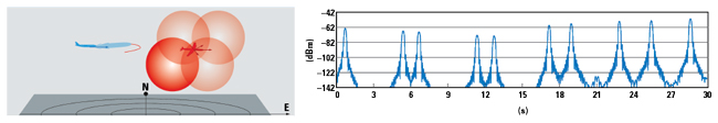
Figure 2 3D flight scenario with the emitter and receiver moving.
HIGH SPEED PDW STREAMING
Ultra-long scenario playtime and real-time changes to the simulation can be achieved by streaming Pulse Descriptor Words (PDW) using a network connection to the VSG, which serves the role of an agile RF signal source. It supports classical unmodulated radar pulses, Barker coded pulses, FMCW signals and any I/Q modulation on the pulse, enabling the most modern, low probability of intercept radars to be simulated. The R&S SMW200A supports PDW rates up to 12 million PDWs per second.
FIELD DEMONSTRATION
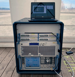
Figure 3 At an OTA demonstration at Tartu Airport in Estonia, the signal generators and amplifier were mounted in a small rack, with the R&S Pulse Sequencer software running on a commercial laptop.
During a live demonstration at the 2019 EW Live event in Tartu, Estonia, a radar simulator from Rohde & Schwarz was operated over-the-air (OTA) with a free-space distance of 1.3 km to the ELINT and radar warning receivers. An R&S SMW200A VSG with two, 20 GHz RF paths controlled by the R&S Pulse Sequencer software served as the signal source (see Figure 3). The SMW200A VSG’s large internal modulation bandwidth of 2 GHz enabled generating radar signals from multiple emitters in a single RF path. Four compact R&S SGT100A RF sources were also integrated into the system to simulate additional radars operating below 6 GHz. This setup supported OTA test scenarios with 10 simultaneous radar emitters between 3 and 9.5 GHz.
Figure 4 shows a signal plan for one simulation. In this scenario, the R&S SMW200A generated six radar signals simultaneously, three in RF path A and three in path B. Splitting radar signal generation between two paths makes it possible to create very realistic scenarios, including those with colliding pulses and highest dynamic range. In RF path A, signals from radar systems with operating frequencies between 5 and 6 GHz were simulated, while path B had signals in the 9 GHz range. Each R&S SGT100A generated one additional radar. The signal plan defined different radar signals, from simple, unmodulated pulses to complex I/Q modulated pulses (e.g., AMOP, FMOP, PMOP, chirps and Barker code pulses). Diverse IPM profiles, such as pulse repetition interval staggering and frequency hopping, were used. A complex, multi-mode radar featuring frequency and time agile operation, as well as diverse antenna patterns and scans, was included.
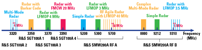
Figure 4 Example signal plan used at the Tartu Airport demonstration. One dual-path R&S SMW200A and four R&S SGT100A VSGs generated 10 simultaneous radar emitters between 3 and 9.5 GHz.
For the EW Live demonstration, the flexibility and powerful performance of the R&S SMW200A and R&S SGT100A VSGs created a full-featured radar simulator. The VSGs demonstrated high performance field testing for relatively low cost and effort using standard components. Added benefits were quick installation of the setup at a remote location and verification of the performance of the systems to be tested.
Rohde & Schwarz
Munich, Germany
www.rohde-schwarz.com