

In Equation (5) the frequency contributions of the incident signal cancel and, depending on the amount of delay, the result is a DC value. In Equation (6), however, as the incident frequency changes, the DC value at the output IF changes. This is the desired result and is the basis of the frequency locked loop. As the source frequency changes slightly, the circuit produces a changing DC voltage. The next steps develop how that changing DC voltage is fed back to the source to compensate for frequency drift.
Remaining Unknowns
The circuit in Figure 3 contains the basic elements to “sense” the error associated with the frequency locked loop of Figure 1. However, it remains insufficient for practical applications; there are too many variables and unknowns. To understand the limitations, it is necessary to further explore Equation (6).
Figure 6 is the output of Equation (6) as a function of frequency, showing that the IF voltage varies sinusoidally. For any given voltage, however, frequency is ambiguous, as illustrated with points A and B. These are at the same voltages but located at different frequencies along opposite slopes. If the voltage begins to increase, it is equally likely to be at point A moving to the left or at point B moving to the right (see Figure 7).
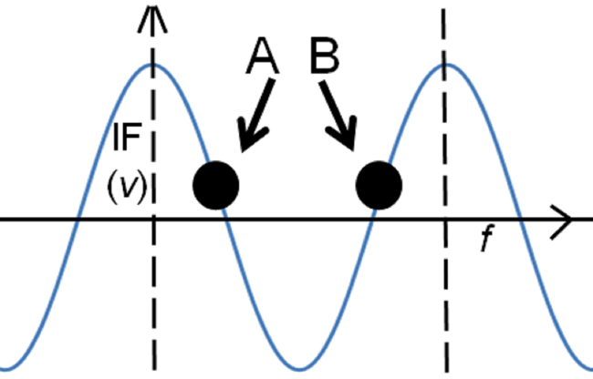
Figure 6 Two points with the same voltage.
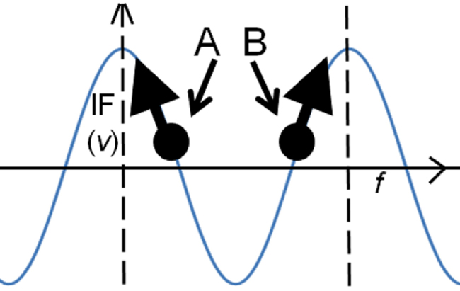
Figure 7 Two moving points with the same voltage.
Adding an IQ Power Splitter
The circuit in Figure 3 combines a delay element with the basic mixer circuit. The circuit in Figure 8 has two new elements: an IQ power splitter and a second mixer. The excitation source and other elements remain the same.
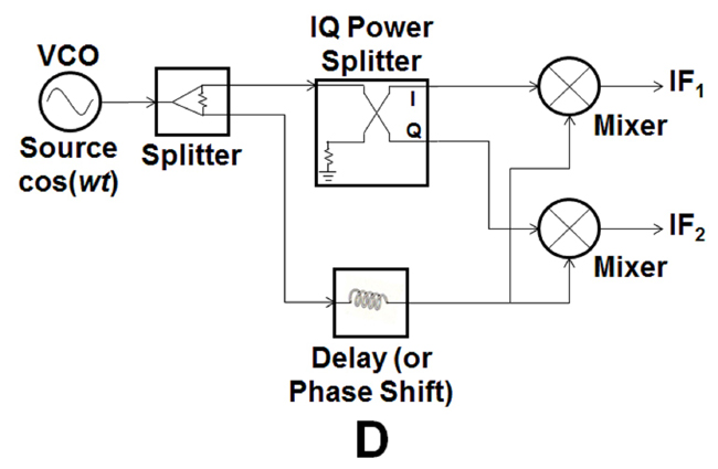
Figure 8 Circuit of Figure 3 with an IQ power splitter and second mixer.
The IQ power splitter gets its name in the following way:
I= in phase (cos)
Q= quadrature (sin)
The term quadrature comes from quad, or four, i.e. four slices of a period. In other words:
¼ λ, where λ is a full wavelength
It is further known that:

An IQ power splitter simply splits a signal in two, one in phase with the source and a second signal 90 degrees out of phase with the source, for short, IQ.
The circuit in Figure 8 is redrawn in Figure 9 and includes some useful equations.
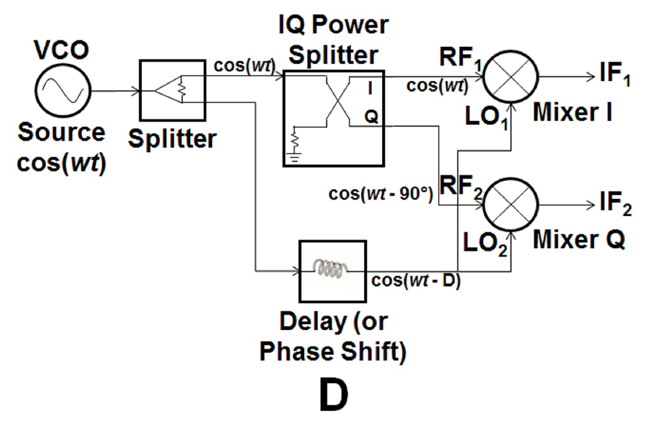
Figure 9 Circuit of Figure 8 with sinusoidal waveforms annotated.
The following can be written:

If the amplitudes (or constants) are appropriately selected, i.e.:

Then Equation (3) can be simplified to:
Similarly:

Selecting amplitudes appropriately such that they become equal to 1, the following is derived:

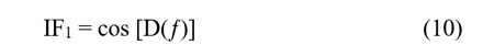
And, as before, the high frequency contributions are filtered out. The equation can be simplified to:
IF2 = cos (D – 90)

The Importance of IF1 & IF2
Figure 10 is a simplified representation of the circuit in Figure 9. If a frequency source is applied, the outputs are two voltages. The voltages are a function of the delay line, which is a function of the source frequency. As the source frequency begins to drift, a change in voltage appears at outputs IF1 & IF2.
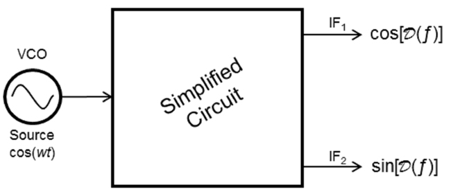
Figure 10 Simplified representation of Figure 9.