
More complex RF transformer topologies, such as transformers with several windings, taps and additional elements, present varying performance dynamics based on the topology and transformer construction. For example, an RF device known as a balun is used to efficiently interconnect balanced (i.e., differential signal) circuits to unbalanced (i.e., single-ended signal) circuits using impedance transformation; it can be realized with an RF transformer. Another device similar to a balun, known as an unun, is used to interconnect unbalanced to unbalanced RF circuits, and it can be realized with an RF transformer. A common balun fashioned from a transformer is a flux coupled balun transformer, constructed by winding separate wires around a magnetic core and grounding one side of the primary winding. The single-ended RF signals entering the primary unbalanced winding undergo an impedance transformation to a differential (i.e., balanced) output through the secondary winding.
RF transformers that include a magnetic core - typically ferromagnets - have several undesirable factors that degrade performance. The magnetizing inductance of the core limits the low frequency performance of the transformer. This inductance is a function of the core permeability, cross sectional area and number of windings around the core. The magnetizing inductance increases the insertion loss at low frequencies and degrades the return loss. The permeability of the core is also a function of temperature; permeability increasing with temperature increases the low frequency insertion loss.
RF Transformer Technologies
The two main types of discrete RF transformers are core-and-wire and transmission line. Additionally, two common types of low profile and compact transformer designs are LTCC and MMIC.
Core-and-Wire RF Transformers

Figure 4 Construction of a wire-wound transformer with magnetic core.
Core-and-wire transformers are fabricated by wrapping conductive wires, typically insulated copper wires, around a magnetic core such as a toroid. There may be one or more secondary windings, which may also be center tapped to enable additional functions. Figure 4 shows an RF transformer made from a toroidal magnetic core and insulated copper windings. Due to the nature of the inductive coupling between the wires and the core, smaller core-and-wire dimensions tend to yield core-and-wire transformers that operate at much higher frequencies than those with larger core-and-wire transformers. However, the smaller size of the compact transformers increases the resistive losses of the windings and the core, resulting in greater insertion loss at lower frequencies.
Transmission Line RF Transformers
Transmission line transformer topologies may include precisely designed transmission lines placed between two mismatched loads or a complex arrangement of several transmission lines. For instance, a length of transmission line can be used to implement an impedance transformation between two mismatched loads. Some transmission line transformers use insulated wires wrapped around ferrite cores, closely resembling typical core-and-wire transformers - often considered core-and-wire transformers. Nonetheless, the following discussion is provided less for categorization than to describe transformer behavior and enhance understanding.
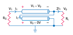
Figure 5 Schematic of an ideal transmission line transformer.
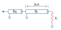
Figure 6 Quarter-wave transmission line transformer.
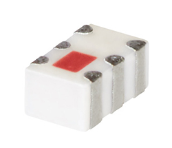
Figure 7 Transformer fabricated with LTCC technology.
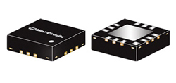
Figure 8 Transformer fabricated with MMIC technology.
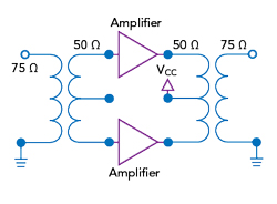
Figure 9 50 Ω balanced amplifier using transformers for impedance matching to 75 Ω.
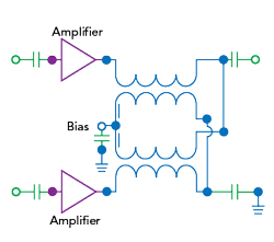
Figure 10 Using a center-tapped transformer to replace bias tees.
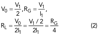
A basic transmission line transformer consists of a two conductor transmission line. The first conductor is connected from the generator to the load, and the other conductor is connected at the output of the first transmission line and the load to ground (see Figure 5). With this configuration, the current flowing through the load is twice the current flowing through the generator, and V0 is half the voltage V1. Hence, the load resistance is only a quarter of the resistance seen at the generator side, yielding a 1:4 transformer, as described by
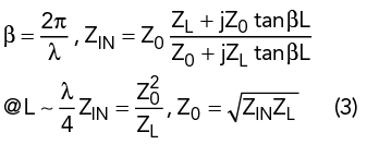
A common version of the transmission line transformer is the quarter-wave transmission line. This topology uses a transmission line with a characteristic impedance that enables impedance matching between the input impedance and the load. The length of a quarter-wave transformer is dictated by the operating frequency, with the bandwidth limited to one octave around the center frequency. Consider a lossless transmission line with characteristic impedance Z0 and length L, connected between an input impedance Zin and load impedance, ZL (see Figure 6). To match Zin with ZL, the characteristic impedance of the quarter-wave transmission line, Z0, is determined by
One advantage of a transmission line transformer is that a significant portion of the interwinding capacitance, along with the leakage inductance, is assumed by the transmission line, which results in a wider operating bandwidth compared to core-and-wire transformers.
LTCC Transformers
LTCC transformers are multilayer components fabricated using a ceramic-based substrate. LTCC transformers use coupled lines acting as transmission lines to achieve impedance transformation and signal conversion from single-ended to balanced. LTCC transformers rely on capacitive coupling, enabling LTCC transformers to operate at higher frequencies compared to ferromagnetic transformers. However, this may lead to performance degradation at low frequencies. One benefit of LTCC technology is the ability to fabricate small and rugged transformers, ideal for high-reliability applications (see Figure 7).
MMIC Transformers
Like LTCC transformers, MMIC transformers are made using 2D substrates with precision layered planar metallization. Typically, MMIC transformers are fabricated using spiral inductors printed on a substrate in a two transmission line configuration, with the lines parallel. A MMIC transformer can be fabricated using a GaAs integrated passive device process (see Figure 8). The precision lithography helps achieve outstanding repeatability, high frequency performance and excellent thermal efficiency.
Transformer Functions & Applications
Depending upon topology, RF transformers serve a variety of functions:
Matching - A transformer can match two circuits with different impedances or provide voltage step-up or step-down of the source voltage. In RF circuits, an impedance mismatch between two nodes causes reduced power transfer and troublesome reflections. The impedance matching transformer effectively eliminates the reflections and provides maximum power transfer between the two circuit nodes (see Figure 9).
Baluns and ununs - Baluns are used to connect balanced and unbalanced circuit sections. For unbalanced lines, an auto-transformer configuration can be used for impedance matching, i.e., an unun.
Bias injection and isolation - An RF transformer can be designed to provide DC isolation between the primary and secondary windings, which is useful for separating RF circuits requiring a DC bias from circuits negatively impacted by a DC voltage. If a DC current is required for a portion of the circuit, a specialized RF transformer can be used to inject current into the signal path. For example, two center-tapped transformers can inject a DC bias and replace two bias tees (see Figure 10).
Other functions - RF transformer designs can be used to provide enhanced common mode rejection for balanced (i.e., differential) circuits. Other topologies can function as a choke, filtering high frequency components from a signal line.
Summary
RF transformers are fabricated using a wide variety of manufacturing methods and diverse materials. They are configured in a myriad of topologies to perform many functions in RF circuits. Depending on the materials, construction and design, RF transformers can be narrowband or wideband, operating at low or high frequencies. Understanding the nuances of RF transformers can help designers optimize a design by choosing the best transformer. Additional articles discussing RF transformers will be published online at www.mwjournal.com.