
This article is the first in a series on demystifying RF transformers. It focuses on introducing RF transformer theory and discusses common RF transformer technologies and applications.
In essence, a transformer is merely two or more conductive paths linked by a mutual magnetic field. When a varying magnetic flux is developed within a core, by alternating current passing through one conductive path, a current is induced in the other conductive paths. This induced current is proportional to the ratio of the magnetic coupling between the two conductive paths. The ratio of the magnetic coupling of the conductive paths with the core determines the induced voltage in the additional conductive paths, providing both an impedance transformation and a voltage step-up or step-down. Additional conductive paths, potentially all with different coupling ratios, may be added to realize various functions, which is why RF transformers are such varied and versatile devices and used widely throughout the RF/microwave industry.
A common implementation of an RF transformer consists of two or more distinct wires wrapped around a magnetic core - or an air core at higher frequencies - which is why RF transformers are often described as the ratio of the number of windings or turns. RF transformers are used for a variety of applications, as the nature of the device allows for various configurations serving different functions, including
- Providing an impedance transformation for impedance matching.
- Stepping up or down a voltage or current.
- Efficiently coupling between balanced and unbalanced circuits.
- Enhancing common mode rejection.
- Providing DC isolation between circuits.
- Injecting DC current.
Several common technologies are used to build transformers, including core-and-wire, transmission line, low temperature co-fired ceramic (LTCC) and MMIC. Each is available in a variety of packages with a range of performance characteristics.
Transformer Theory
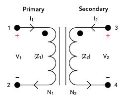
Figure 1 Schematic of an ideal transformer.
Though not realistic for actual applications, a model of the ideal transformer illustrates the fundamental behavior of transformers (see Figure 1). Ports 1 and 2 are the input of the primary winding, and ports 3 and 4 are the output of the secondary winding. From Faraday’s Law, the current through the primary winding creates a magnetic flux through the mutual magnetic field of the core, inducing a proportional current and voltage in the secondary winding. Both the current and voltage developed are proportional to the ratio of the windings or the magnetic coupling between the windings and the core. Hence, the secondary impedance is a function of the square of the windings ratio multiplied by the impedance of the primary. The operation is described by the following:
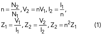
where I1, V1 and Z1 are the current, voltage and impedance through the primary winding; I2, V2 and Z2 are the current, voltage and impedance through the secondary winding; N1 is the number of turns in the primary winding; and N2 is the number of turns in the secondary winding.
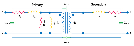
Figure 2 Transformer model with parasitic elements.
A real transformer includes several parasitic resistances, inductances and capacitances, both mutual and self-parasitic capacitances. Figure 2 shows a lumped-element model of a non-ideal RF transformer, which depicts the parasitic resistances and inductances of the two windings, as well as the core resistive losses and the windings’ active inductance. The parasitics cause an actual transformer to operate over a limited bandwidth, with insertion loss and limited power handling (see Figure 3). The performance also depends on frequency, temperature and power.
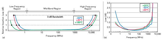
Figure 3 Theoretically, a transformer has a bandpass frequency response (a) which measurements confirm (b).
An actual RF transformer’s lower cutoff frequency is dictated by the winding’s active inductance, and the high frequency cutoff is dominated by the inter-winding and intra-winding capacitance. The insertion loss in the operating bandwidth is a product of the ohmic losses in the primary and secondary windings, as well as the dissipation within the core. As the ohmic losses tend to be a function of frequency and temperature, the transformer’s effective operating bandwidth is limited by these factors. Several RF transformer types introduce leakage inductances due to incomplete magnetic coupling between the windings. As the reactance of the leakage inductance is proportional to frequency, these parasitics reduce the return loss at high frequency and increase the insertion loss at lower frequency.