
Phase-locked oscillators (PLO) are stable frequency sources with inherently low phase noise and spurious signals. They are widely used for frequency generation in radar, communications and other applications. This article reviews the background, architectures and pertinent parameters of PLOs.
Much RF/microwave literature covers the design and application of the phase-locked loop (PLL), a feedback system designed to closely track and match the phase of two RF sources: a reference oscillator and voltage-controlled oscillator (VCO). A PLO is meant to function as a stable microwave source or local oscillator (LO) and often leverages an analog or digital PLL to impart onto the VCO the frequency stability and phase noise of a crystal oscillator or other low noise reference.
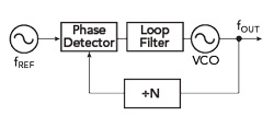
Figure 1 Phase-locked loop.
In a simple PLL (see Figure 1), the output of a VCO is fed in a feedback loop through a divider, where the divider generates one output pulse for every N input pulses. The output of the divider is fed to a phase or error detector that detects the phase between the output of the divider and the output of the reference. The phase detector produces a pulsed error signal representing the phase difference between the reference and the frequency divided VCO. This error is filtered in a lowpass filter, also known as the loop filter, and controls the VCO, ultimately locking it to a specific frequency, which is related to the phase.
In a radar or communications system, a LO with poor short-term stability rapidly changes its output level and phase, and adjacent frequency components or sidebands appear due to the amplitude and phase modulation. The sidebands of this noisy LO are present at the IF and compromise receiver sensitivity. A weak received signal buried in the phase noise would be undetected. The frequency generation process often results in a poor signal-to-noise ratio due to the phase noise sidebands. For a VCO, this process integrates the PLL, frequency multipliers, dividers and other components used in generating the LO frequency output, with the phase noise profile shaped by these components. A PLO leverages the good short-term stability and close-to-carrier performance (high Q) of a crystal oscillator or other stable source by using it as a reference for the VCO, which has comparatively poor short-term stability, yet a good noise floor far from the carrier.
Direct Synthesis, Indirect Synthesis and Digital Synthesis
A frequency synthesizer is generally defined as a device that can generate multiple frequencies from a single frequency reference. A PLO can be considered a fixed frequency synthesizer that generates a stable output frequency regardless of temperature drift, vibration and aging. Frequency synthesizers can be implemented using one of three topologies: direct synthesis, indirect synthesis or direct digital synthesis.
Some systems generate an LO frequency using direct synthesis. In one implementation, the reference oscillator frequency (typically from a crystal) is multiplied in several stages (see Figure 2), where each multiplier stage requires an amplifier and filter to reach the required drive level and minimize spurious signals. This architecture can become cumbersome, with many components and potential failure modes, and multipliers often use step recovery diodes, which are prone to instability and difficult to tune.1 In direct synthesis, filter design and alignment are crucial to minimize spurious signals.
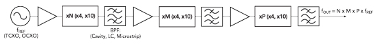
Figure 2 Direct frequency synthesis.
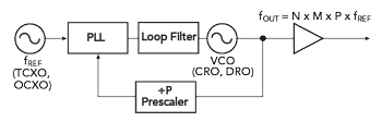
Figure 3 Indirect frequency synthesis.
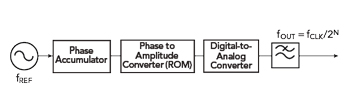
Figure 4 Direct digital synthesis.
More often, indirect synthesis is employed, typically in the form of a PLL oscillator (PLLO), where the output frequency is divided and compared directly with the phase of a reference oscillator. This way, the output frequency is a rational multiple of the reference frequency. A common topology (see Figure 3) includes a temperature compensated crystal oscillator (TCXO) or oven controlled crystal oscillator (OCXO) as a reference, with a VCO such as a dielectric resonator oscillator (DRO) or coaxial resonator oscillator (CRO). This architecture is far less complex than direct synthesis and provides low phase noise and spurious signals.
With direct digital synthesis (DDS), an analog reference signal determines an invariant sampling interval, from which a sequence of signal amplitudes are calculated and output as digital codes (see Figure 4). The digital signal is sent to a digital-to-analog converter (DAC) and the output is filtered to generate an analog signal at the desired frequency. While this method is more frequency agile than the previous approaches, it generally operates only at lower frequencies due to increasing power consumption with increasing frequency. The DDS also produces more spurious emissions than its analog counterparts, caused by numerical truncation and DAC errors.
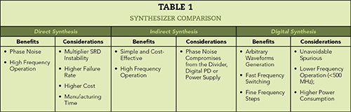
Table 1 summarizes the benefits and considerations of these three architectures.
Indirect Synthesis: Digital vs. Analog PLL
A PLLO can use either a digital PLL (DPLL) or analog PLL (APLL). The analog implementation includes all the conventional PLL components with one major difference: the phase detector is an analog multiplier (mixer) instead of a digital phase frequency detector (PFD). The analog approach involves several frequency multiplication stages (e.g., x4, x10) to generate the required frequency to compare with the output frequency of the microwave oscillator (see Figures 5a and 5b). Phase comparison uses an analog phase detector (e.g., a four quadrant multiplier or diode ring mixer). This topology may have an advantage for space applications, where analog components have an inherent immunity to radiation effects or signal events that may affect digital components (e.g., latch up).1
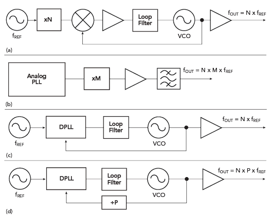
Figure 5 PLO architectures: analog PLL (a), analog PLL with multiplier (b), digital PLL (c) and digital PLL with prescaler and multiplier (d).
The main issue with this approach is the potentially large multiplication ratio required for high frequencies, i.e., X-Band and above. Each multiplication stage requires amplification and filtering to minimize spurious signals, and the added sub-circuits introduce potential failure modes, such that these PLOs are less reliable in many circumstances. Another disadvantage is the phase noise of the reference source is multiplied by the analog PLL.
A digital PLL (DPLL) uses a digital frequency divider (either integer- or fractional-N) for the main and reference signals (see Figures 5c and 5d). Digital phase detectors such as PFDs are used with active and passive filtering to achieve the desired phase noise and spurious performance. This implementation lends itself to greater inherent reliability, due to its relative simplicity, and offers a cost benefit from the ease of manufacturing. The main issue is a relatively higher noise floor. Multi-loop architectures are often used to mitigate this limitation.
The DPLL should not be confused with the all-digital PLL (ADPLL), which can include a DDS. The ADPLL eliminates all analog circuitry, comprising a digital loop filter and digitally controlled oscillator. Some PLOs can incorporate an ADPLL or a DDS to provide high frequency resolution.
Dual-Loop Architectures
Dual-loop PLOs contain two PLLs, where the first stage provides the reference frequency for the second stage (see Figure 6). The signal output from the first stage is divided down to an appropriate frequency to be the second stage reference. Most PLO designs assume a 10 or 100 MHz reference. This architecture is particularly useful when the input reference is an unknown quantity that must be manipulated to obtain a precise output frequency. Another benefit is the ability to mitigate the spurs generated by the digital dividers, where the frequencies of the spurs are based on the division. With the dual-loop architecture, the division number is reduced due to the fixed offset frequency. This approach is also helpful for high frequency loops, which tend to require a narrower loop bandwidth to limit the phase noise at the output. With a dual-loop PLO, the loop bandwidth can be larger to increase the locking speed of the PLO, while suppressing the VCO output phase noise close to the carrier.
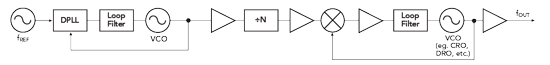
Figure 6 Dual-loop PLO with both digital and analog PLLs.
Fundamental Oscillator Choice
The choice of the fundamental oscillator depends on the output frequency and required noise performance. Up to S-Band, a crystal oscillator offers excellent phase noise performance close to the carrier. This, however, does not suffice at higher frequencies. Here, a CRO up to C-Band or DRO up to X-Band can be used. A VCO can be used up to Ka-Band with the trade-off of poorer phase noise. As stated earlier, this can be mitigated in a multi-loop design. A DDS can generate the output frequency with much higher frequency resolution and lower phase noise than a VCO; still, spurious emissions and power consumption must be considered.
The selection of the fundamental oscillator may also depend on size constraints. A DRO, for example, may be unreasonably large at lower frequencies. A DDS can be implemented with CMOS technology, achieving low cost and a small form factor. However, the size benefit generally diminishes above 500 MHz, due to the increasing power consumption and need to dissipate the heat. A VCO can be implemented as a MMIC, including the PFD and digital divider. A PLO will typically be built as a microwave integrated circuit on a thin film substrate; this allows for greater output power at moderate frequencies.
Conclusion
A PLO supplies an RF signal with the high spectral purity required for many applications, from LOs in radar and communications systems to high speed clock signals to clean sources in test and measurement equipment. PLOs can be implemented with many architectures, and the choice will impact the output frequency, phase noise, spurious, harmonics and output power. Each has its respective pros and cons.
References
- B. Hitch and T. Holden, “Phase-Locked DRO/CRO for Space Use,” Proceedings of the International Frequency Control Symposium, May 1997.
- T. J. Rouphael, “RF and Digital Signal Processing for Software-Defined Radio: A Multi-Standard Multi-Mode Approach”, Elsevier Newnes, 2009.