
The effects on electrical performance of a choke-fed monopole antenna placed coaxially within a quadrifilar helix antenna are presented. A specific application of this antenna configuration is for reception of S-band digital audio broadcasts. The quadrifilar antenna has a beam coverage optimized for satellite reception at elevation angles >= 25° above the horizon. The purpose of the monopole antenna is to receive linearly-polarized signals from terrestrial basestations in the event of signal fading of the primary satellite source, as might occur in urban canyons. The antenna is designed to be compact and intended for external mounting on a subscriber's automobile.
Charles D. McCarrick
Seavey Engineering Associates Inc.
Pembroke, MA
Nowadays, innovation in antenna design has less to do with theory than with implementation. To be of consumer-quality, antennas must be compact, rugged and economical. Diversity can be a highly valued feature, particularly if it helps the antenna meet the above criteria. To this end, a combination monopole/quadrifilar helix configuration has been investigated that has application as a subscriber antenna for the reception of digital audio satellite broadcasts. This article describes such a device operating over a frequency band of 2326 MHz ±10 MHz. The quadrifilar helix receives the satellite signal directly, while the monopole is only engaged during situations of inadequate signal strength, such as might occur in urban canyons. Under such conditions, the reception duty is handed off to the monopole, which can receive the broadcast from terrestrial basestations located strategically within the urban area. Studies indicate that vertically polarized signals ensure optimal transmission in multi-path environments of this sort, so the monopole is the natural complement to a vertically polarized basestation. The antenna configuration is made compact by placing the monopole coaxially within the quadrifilar helix and carefully positioning it so as to minimize electrical performance degradation between the two. The two antennas are described, first separately and then integrated together as a single unit.
THE QUADRIFILAR HELIX ANTENNA
Quadrifilar helix antennas have the unique attribute of producing a circularly polarized conical beam while maintaining a relatively slender and compact form factor.1 These antennas are becoming increasingly popular and have been produced in substantial volumes for such applications as global positioning receivers, handheld satellite phones and radio-communication terminals. The quadrifilar helix is relatively insensitive to a conducting element placed within its core, provided that the diameter of the internal element is reasonably less than that of the host quadrifilar. Generally, the diameter ratio between the two antennas should not exceed 1:3;2 however, short sections (¾ λ/4) of the internal conductor resulting in a diameter ratio of 1:2 are permissible if properly located. This leads to the present topic, in which a λ/4 choke is placed within a quadrifilar helix of twice the diameter for the purpose of creating a coaxial monopole.
Quadrifilar Helix Test Model
Designing the quadrifilar helix is a straightforward procedure; however, special care must be taken to ensure that the structure is properly excited for optimum performance. The main complexity of these antennas lies within the feed/matching network design. After selecting the helix parameters that give the desired beam coverage, the mutual input impedance of each winding must be characterized so that an appropriate feeding and matching network can be implemented.3 The feeding network provides an equal distribution of RF signal power to the four helix windings in quadrature phase rotation so as to excite the proper beam mode. The matching network is a set of four reactive impedance transformers, one for each winding.
The geometry for the quadrifilar helix under consideration is shown in Figure 1. The helices have a winding sense for left-hand circular polarization, and an angular pitch for an elevation coverage of 25° to zenith. The selected quadrifilar dimensions are 2" pitch, 0.75" diameter and 2 turns for a developed length of 4".
|
|

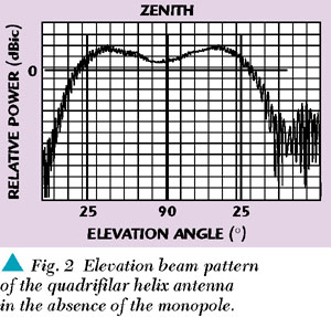
The antenna was fabricated as a printed circuit and etched on a 5-mil substrate of Teflon™-fiberglass. The measured input for each winding was 28 Ω within the frequency band of interest, so a matching network of four 37 Ω quarter-wave lines was incorporated to match the antenna to a 50 Ω input. A branchline coupler was etched together with the matching network and helix winding to complete the circuit. The feeding/matching network adds an additional 0.625" to the overall antenna height. A typical beam pattern cut in the elevation plane measured for this antenna in the absence of the monopole is shown in Figure 2. The gain between 25° and zenith is at minimum 2 dBic, with a peak gain of 3.4 dBic occurring around 45°. Ellipticity is seen to be less than 2 dB within the coverage region.
|
|
THE MONOPOLE ANTENNA
The monopole antenna used here is actually a form of dipole antenna whose reflective element is a quarter-wave choke. The design consists of a 4" length of UT85 semi-rigid coaxial line terminated with a 50 Ω SMA connector on one end, and has a section of the outer conductor removed at the other end to expose the center conductor. This forms a sort of rudimentary dipole element. A choke is used to sheath the outer conductor to prevent currents from flowing along its length and producing undesirable radiation.
Choked Monopole Antenna Test Model
The geometry for the choked monopole under consideration is shown in Figure 3. The selected dimensions are 0.93" length for the exposed center conductor (monopole), 1.2" length and 0.375" diameter for the choke. The choke is fabricated from a 10-mil thick wall brass tube, and is soldered to the coaxial line outer conductor as shown.
|
|
|

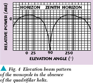
The beam radiation pattern for the choked monopole antenna in the absence of the quadrifilar is shown in Figure 4. The gain of the antenna at the horizon is approximately 1.5 dBil and 1.9 dBil at 25° above elevation. This region of coverage is deemed sufficient for terrestrial reception in urban areas.
COMBINING ANTENNAS
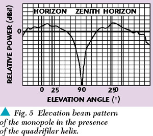
Placement of the monopole within the quadrifilar helix is critical. If improperly located, coupling between the two antennas will result in severe degradation of the radiation patterns, particularly for the monopole. In addition to being axially concentric, the feedpoint of the monopole (the point along the axis where center conductor and choke coincide) must be displaced vertically below the top of the quadrifilar by a specific distance. This distance was predicted by moment method modeling then verified through experimentation. Properly located, the quadrifilar helix patterns are virtually unaffected, while the monopole patterns suffer only marginal degradation, as shown in Figure 5. In the present case, the optimal location was found to be 0.42" below the top of the quadrifilar, which means that the monopole protrudes 0.51" out the top of the structure. The combined antenna configuration is sketched in Figure 6.
|
|
|

CONCLUSION
A dual antenna configuration has been proposed with the intent of giving both satellite and terrestrial reception capability. This was accomplished by placing a choke-fed monopole within the core of a quadrifilar helix, and finding the location giving optimum performance. Some rules of thumb with regards to diameter ratios between the two antennas were discussed and verified through experimentation to hold true. *
References
1. C.C. Kilgus, "Shaped-conical Radiation Pattern Performance of the Backfire Quadrifilar Helix," IEEE Transactions on Antennas and Propagation, Vol. AP-23, May 1975, pp. 392397.
2. W.T. Patton, "The Backfire Bifilar Helical Antenna," Technical Report No. 61, Aeronautical Systems Division, Wright-Patterson Air Force Base, September 1962.
3. C.J. Mosher, "The Impedance Behavior of a Quadrifilar Helical Antenna," Master of Science Research Report, UMass Amherst, February 1997.
|
|
 Charles D. McCarrick holds the position of chief scientist and heads up the consulting division at Seavey Engineering Associates Inc. He received his BSEE degree (1987) and MSEE degree (1989) from Southeastern Massachusetts University and his PhD degree (1999) from the University of Massachusetts at Dartmouth. Since joining Seavey Engineering Associates Inc. in 1989, Dr. McCarrick has been responsible for the development of a wide range of antennas, and holds four patents.