
Generally ∣ΓB∣ is close to unity. The phase of the reflection coefficient must be the same on both ports. If it is not, the references planes must be shifted until phase equality is found. The phase of ΓBin the calibration kit must be known within 90 degrees.

CALCULATIONS
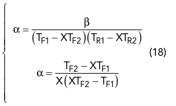
From Equations 6 and 10 and 9 and 13:

If

we obtain two expressions for α:
That gives a second degree equation in X:
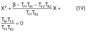
There are two solutions for this equation, and both values for ∣X∣ are close to unity for a line with small losses, making it difficult to choose the right solution. It is safer to choose ∣α∣ << 1.

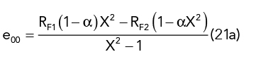
From Equations 5 and 9, the directivity (e00 and e33) is the ratio of the leakage of the incident signal to the reflected signal:


From Equations 14 and 6:

From Equations 15 and 9:
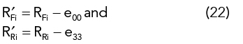
So
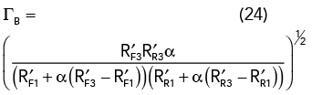
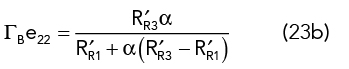
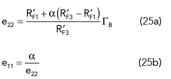
The port mismatch (e22 and e11) is
All the following results correspond to transmission elements. They only need to be known by their products.
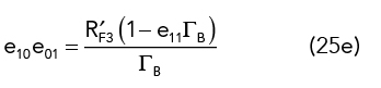
Transmission tracking:
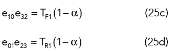
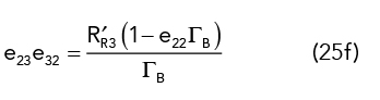
Reflection tracking:
DE-EMBEDDING TO EXTRACT THE DUT
Sij corresponds to the extracted behavior of the DUT alone. The de-embedding technique described below extracts the parameters of the DUT by eliminating the embedded system of errors.
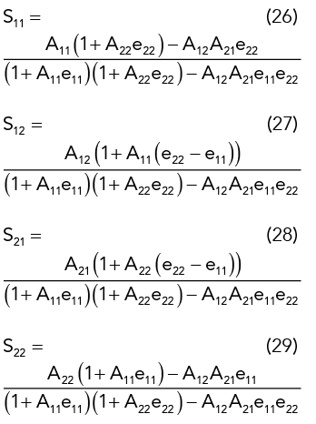
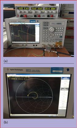
Figure 3 VNA (a) and Smith chart display of S11 (b).
With representing the S-parameters of the measured DUT between the VNA reference planes,

VALIDATION
A 4 to 8 GHz amplifier with 10 dB nominal gain was used as a DUT and measured with a VNA to validate the TRL calibration method and efficiency (see Figure 3). Figure 4a shows the magnitude of the DUT’s transmission coefficient, ∣S21∣, and Figure 4b shows its phase. The traces correspond to S21 measured without calibration, S21 measured using the calibration algorithm internal to the VNA and S21 calculated using the method described in this article, showing virtually no difference between the two calibration methods. Figure 4c shows S11 plotted on the Smith chart; the two traces represent measurements using the VNA’s built-in calibration and the calculated values using the method described in the article. All the curves show coincidence between the analytically calculated values of S11 and S21 and those determined by the VNA’s internal calibration algorithm.
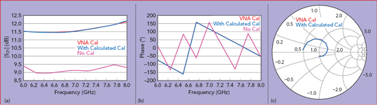
Figure 4 |S21| (a), ∠S21 (b) and S11 (c) measurements using the internal VNA and calculated TRL calibrations.
CONCLUSION
Analytic calculations associated with the well-known TRL calibration method reduce calculation complexity compared with the classical matrix formalism.3 This approach can be extended for further measurement configurations, particularly for differential inputs and outputs.6-7
References
- G. Antonini, A. C. Scogna and A. Orlandi, “De-Embedding Procedure Based on Computed/Measured Data Set for PCB Structures Characterization,” IEEE Transactions on Advanced Packaging, Vol. 27, No. 4, November 2004, pp. 597–602.
- C. J. Ong, A. Tripathi, D. Miller and L. Tsang, “De-Embedding a Device Under Test (DUT) Using ‘Thru’ Measurements,” Electrical Performance of Electronic Packaging, October 2003.
- H. J. Eul and B. Schiek, “Thru-Match-Reflect: One Result of a Rigorous Theory for De-Embedding and Network Analyzer Calibration,” 18th European Microwave Conference, September 1988.
- G. F. Engen and C. A. Hoer, “Thru-Reflect-Line: An Improved Technique for Calibrating the Dual Six-Port Automatic Network Analyzer,” IEEE Transactions on Microwave Theory and Techniques, Vol. 27, No. 12, December 1979, pp. 987–993.
- J. A. Reynoso-Hernandez, M. A. Pulido-Gaytan, A. Zarate-de Landa, J. E. Zuniga-Juarez, J. R. Monjardin-Lopez, A. Garcia-Osorio, D. Orozco-Navarro, J. R. Loo-Yau and M. C. Maya-Sanchez, “Using Lines of Arbitrary Impedance as Standards on the TRL Calibration Technique,” 81st ARFTG Microwave Measurement Conference, June 2013.
- A. Ferrero and U. Pisani, “Two-Port Network Analyzer Calibration Using an Unknown Thru,” IEEE Microwave and Guided Wave Letters, Vol. 2, No. 12, December 1992, pp. 505–507.
- B. Hofmann and S. Kolb, “A Multistandard Method of Network Analyzer Self-Calibration Generalization of Multiline TRL,” IEEE Transactions on Microwave Theory and Techniques, Vol. 66, No. 1, January 2018, pp. 245–254.