
The traditional method to tune Faraday rotation isolators is to use ferrites substantially longer than the minimum required length and adjust the magnetic bias field to achieve a precise 45 degree rotation. This is a useful way to tune the isolator, but it comes at the cost of increased insertion loss: the ferrite is longer and unsaturated ferrites have higher loss per unit length.3,7 In this precisely tuned state, isolators are sensitive to stray magnetic fields, which can cause under- or over-rotation of the signal. While a ferromagnetic sheath is typically employed to channel stray magnetic fields away from the ferrite, even with a sheath, there is some sensitivity.
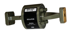
Figure 6 Faraday rotation isolator with extruded waveguide twist.
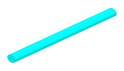
Figure 7 Cored alumina cylinder with resistive layer.
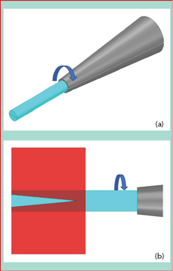
Figure 8 Chucked alumina cylinder (a), rotating during cold laser ablation (b). The red area shows the exposure to the laser.
Micro Harmonics uses a saturating magnetic bias field and the minimum possible ferrite length to yield the minimum loss in the ferrite core. The magnetic bias fields are measured to ensure ferrite saturation, and magnetic armatures are used to achieve a focused, uniform bias field in the ferrite. Figure 5 shows the measured magnetic bias field near the surface of a ferrite. The measured peak value exceeding 2000 Oe, is substantially more than required for saturation. Only stray magnetic fields with a very strong axial component in the opposite polarity will degrade signal rotation.
Minimizing Waveguide Loss
Because the EM field is rotated by 45 degrees as it passes through the ferrite, it is necessary to realign the flanges. Traditionally, this is accomplished by twisting extruded waveguide as shown in Figure 6, where the twist is implemented over a sufficiently long distance to avoid damaging the extruded guide. In the WR10 through WR3.4 bands, the total length of extruded waveguide is typically more than 2 in. Micro Harmonics’ designs replace the extruded twist with machined twist steps substantially shorter, which have broadband performance and reduced waveguide loss. Using this approach, the total flange-to-flange length of a WR3.4 isolator is only 0.45 in. For WR10, the reduction in waveguide loss is only 0.2 dB; however, for WR3.4, the loss reduction is close to 1 dB.
CONE FABRICATION
One of the biggest challenges at higher frequencies is fabricating the alumina cones. The traditional method begins by laminating two alumina plates together with a resistive layer at the interface. The plates are turned on their sides and cored, producing alumina cylinders with a resistive layer bisecting the central axis (see Figure 7). The cylinders are then ground to a cone shape. Using this approach, tip diameters less than 0.004 in. are difficult to achieve, as few machinists can fabricate the cones for WR4.3 and WR3.4 waveguide isolators - the difficulty is even greater for WR2.8 and WR2.2.
Micro Harmonics is experimenting with alternative techniques to form the smallest cones by using cold laser ablation. This approach is appealing because no pressure is applied to the alumina; the process uses no heating, which can damage the epoxy and resistive layers; and forming cones with very small tips may be feasible. The cored cylinders have two ends that are flat and orthogonal to the central axis and suitable for cone bases. The alumina cylinder is then chucked and rotated (see Figure 8), and as material is ablated, the cone eventually detaches from the cylinder.
Diamond Heatsinks
In most commercial Faraday rotation isolators, the ferrite and cones are suspended by a pair of washer-shaped supports (see Figure 9). The cone/ferrite assembly is inserted through the inner support holes and attached with a non-conductive epoxy. The support material is typically biaxially-oriented polyethylene terephthalate (BOPET), Styrene, a resin or some other material with a low dielectric constant and low loss at mmWave frequencies. Materials with these characteristics are generally thermal insulators, thermally isolating the cones and ferrite from the metal block.
In an isolator, absorbed power from the reverse traveling wave is converted to heat energy in the input cone. Very little of this heat can be channeled away by thermal conduction through the washer-shaped supports; rather, it must be dissipated by radiation or convection through the surrounding air. If too much reverse power is incident on the device, the resistive layers are subjected to high heat levels and may be damaged. Higher power sources becoming available has renewed interest in improving the power rating of the isolator.
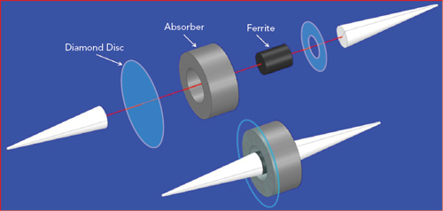
Figure 9 Exploded view showing the cones, absorber, ferrite, support washer and diamond disc.
Micro Harmonics has addressed this by replacing the input support washer with a uniform, high grade, optical chemical vapor deposition (CVD) diamond disc, shown in Figure 9. The thermal conductivity of diamond is near 2200 W/mK, more than 5x higher than copper. The diamond disc is sandwiched between the base of the input cone and the ferrite, in intimate contact over the entire area of the cone base, which is the optimal location for the diamond disc since it is the region subject to the highest heat (see Figure 10). The diamond disc is attached to the metal waveguide block over its entire periphery, providing an excellent conduit to channel heat from the resistive layer. The arrows in the figure illustrate the heat flow, showing this topology is superior for thermal conduction. This isolator design will handle higher reverse power levels while maintaining lower core temperatures, improving reliability.

Figure 10 Thermal path through the diamond support disc.
Cryogenic Applications
NASA recently awarded Micro Harmonics a contract to develop isolators optimized for cryogenic temperatures. In addition to the low temperature thermal stress, the substantial temperature dependence of the ferrite saturation magnetization is also a challenge. The measured isolation of a WR10 isolator drops from 30 dB at 290 K to 14 dB at 77 K, caused by a 10 degree over-rotation of the EM fields from higher magnetization at 77 K.
Ferrite magnetization follows a modified Bloch law:
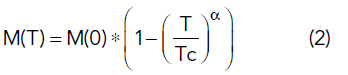
where M(T) = magnetization, M(0) = magnetization at 0 K, Tc = Curie temperature and α = the temperature exponent. The Curie temperature is the temperature at which materials lose their permanent magnetic properties. The Bloch law typically follows an α = 3/2 form,8 although evidence in the literature suggests that a modified Bloch law with α = 2 is a better fit for nickel spinel ferrites.9-10 The decrease in magnetization at higher temperatures is caused by the increasing excitation of spin waves, which makes it more difficult to align the magnetic dipoles.
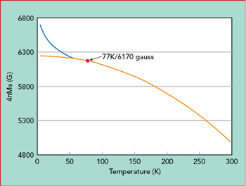
Figure 11 Temperature dependence of the saturation magnetization.
Fitting measured data to a modified Bloch law with M(77 K) = 6170 G, Tc = 648 K, M(0 K) = 6250 G and α = 2.07 yields the solid curve in Figure 11. Some literature says the magnetization can depart from the modified Bloch Law at temperatures below 50 K, depending on the ferrite particle size (the blue curve in the figure).10
SUMMARY
This article described a new and innovative design approach for mmWave isolators, which has been used to develop isolators for every waveguide band from WR15 through WR3.4, i.e., 50 to 330 GHz. The designs employs diamond heatsinks for improved thermal conduction and achieve typical insertion loss less than 1 dB for WR10 (75 to 110 GHz) and less than 2 dB for WR3.4 (220 to 330 GHz) - a significant improvement over the previous state-of-the-art. The same design approach is being used to develop isolators for WR2.8 (265 to 400 GHz) and WR2.2 (330 to 500 GHz). NASA is also funding development of mmWave isolators for cryogenic systems.
Acknowledgments
Micro Harmonics would like to thank NASA for the continued support of this work through research contracts NNX15CP37P, NNX16CP07C and 80NSSC18P2018.
References
- N. R. Erickson, “Very Low Loss Wideband Isolators for mm-Wavelengths,” IEEE MTT-S International Microwave Symposium Digest, May 2001, pp. 1175–1178.
- C. E. Barnes, “Broadband Isolators and Variable Attenuators for Millimeter Wavelengths,” IEEE Transactions on Microwave Theory and Techniques, Vol. 9, No. 6, November 1961, pp. 519–523.
- D. Pozar, Microwave Engineering, Wiley.
- B. Lax and K. Button, Microwave Ferrites and Ferrimagnetics, McGraw Hill.
- C. A. Balanis, Advanced Engineering Electromagnetics, 2nd Edition, Wiley, 2012.
- Ansys Corp., “Ansys HFSS–3D Electromagnetic Field Simulator for RF and Wireless Design,” www.ansys.com/products/electronics/ansys-hfss.
- N. G. Sabri, “Nonreciprocal Propagation in Ferrite Medium and Their Applications–Microwave Circulator,” International Journal of Computational Science and Electrical Engineering, Vol. 1, No. 2, 2013.
- C. Kittel, Introduction to Solid State Physics, Wiley.
- R. N. Bhowmik and K. S. Aneeshkumar, “Low Temperature Ferromagnetic Properties, Magnetic Field Induced Spin Order and Random Spin Freezing Effect in Ni1.5 Fe1.5 O4 Ferrite; Prepared at Different pH Values and Annealing Temperatures,” Journal of Magnetism and Magnetic Materials, Vol. 460, August 2018, pp. 177–187.
- K. Maaz, A. Mumtaz, S. K. Hasanain and M. F. Bertino, “Temperature Dependent Coercivity and Magnetization of Nickel Ferrite Nanoparticles,” Journal of Magnetism and Magnetic Materials, Vol. 322, No. 15, August 2010, pp. 2199–2202.