
Their F-Series is a hybrid reverberation-anechoic chamber capable of providing a blend of both worlds (see Figure 5). The RC mode provides easy, fully-automated overnight testing of 4G and 5G OTA while the AC mode incorporates all 3GPP-permitted OTA test methods (IFF, NFTF and DFF) for DUTs of up to 1.5 m.
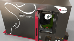
Figure 6 EMITE H-Series 600 MHz to 110 GHz small anechoic chamber including climatic enclosure.
The H-Series is a small anechoic chamber intended to simultaneously test FR1 and FR2 frequency combinations using a combined CATR, spherical near-field (SNF) and DFF test system with the only climatic foam enclosure in the market for testing wireless OTA under both temperature and humidity conditions (see Figure 6). Temperature range from −40°C to 90°C with fluctuation of about ±0.5°C and heating and cooling change rates of 2°C to 4.5°C per minute, and humidity range from 10 to 98 percent relative humidity with fluctuations of ±0.5 to ±3 percent relative humidity are available.
ETS-Lindgren Solutions
Labs with current ETS-Lindgren OTA systems or those manufactured by others will be pleased to know that an upgrade package for 5G testing in the sub-6 GHz, FR1 band is available. This upgrade is economical and backward compatible, providing a three generation OTA system covering 5G, 4G and 3G, if so equipped.
For 5G FR2 mmWave OTA, ETS-Lindgren offers the AMS-5700 series of OTA test chambers (see Figure 7). The AMS-5700 series is highly flexible, offering one system serving multiple projects and use cases. The 5700 series offers direct and indirect far-field configurations covering any array size up to 60 cm. The AMS-5703 is designed with a large quiet zone and unique positioning system to accommodate future CTIA phantom test requirements.
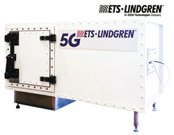
Figure 7 ETS-Lindgren’s table top AMS-5700 OTA test chamber.
ETS-Lindgren also offers custom solutions: one recent ETS-Lindgren project enabled end-to-end data throughput, MIMO and beam steering performance to be measured on gNBs linked to moving UEs. Another complex automotive project provided vehicle to everything (V2X) measurement and optimization results from dozens of antennas and sensors integrated in an autonomous vehicle.
Keysight Solutions
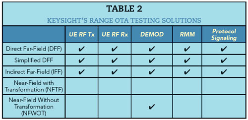
Keysight offers a portfolio of OTA solutions based on the workflow from R&D to device acceptance. A typical solution consists of measurement software, a network emulator to emulate a 5G gNB and a channel emulator to emulate the radio conditions. For FR2, these solutions include OTA measurement systems, typically adding RF enclosures, probe and link antennas, different DUT positioners and associated control software. Keysight’s offerings address the different test approaches and the varying needs for modems, antennas, integrated devices and base stations. OTA tests are required from R&D through design validation, protocol and RF/RMM conformance testing and device acceptance testing. Keysight supports the wide range of solutions shown in Table 2.
Keysight has CATR solutions that offer IFF measurements for RF, RF parametric testing and antenna pattern measurements, well suited for testing antennas, phones, phablets, tablets, laptops and small 5G gNBs. To test devices under real world operating conditions, a solution needs to emulate different directions of arrival of the 5G signal, i.e., emulating the spatial characteristics of the environment. For this, Keysight models signal from the base station (gNB) to the device. Their multi-probe anechoic chamber solutions are good for understanding how a device operates in the spatial environment with multiple simultaneous radiated beam angles (see Figure 8). This solution utilizes the Keysight UXM 5G Wireless Testset, PROPSIM F64 channel emulator and performance network analyzers for testing the device under real world conditions for different key performance indicators like throughput, handover, etc.
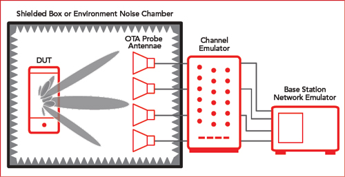
Figure 8 Keysight’s multiprobe anechoic chambers (MPAC) solution.
MVG Solutions
MVG offers multi-probe systems based on rapid sampling, using probe arrays of the radiated near field in amplitude and phase on a closed surface around the device. The far-field performance of the device is determined from near-field to far-field transformation. The exact knowledge of the amplitude and phase of the radiating device gives access to important investigative features on the device behavior through post processing.
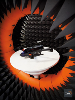
Figure 9 MVG’s multi-probe system testing a drone.
As the electrical size of devices and systems at 5G frequencies increase, the sampling required for exhaustive testing of the devices becomes a burden to the users, as the testing time increases. The multi-probe systems from MVG enable much faster testing than traditional single probe systems allowing users to fully characterize their devices within much more reasonable times, enabling in-the-loop research and development activities (see Figure 9).
When integrating antennas on larger electrical devices, as is the case for the small arrays integrated on handheld 5G devices, the coupling phenomenon between antennas can significantly alter device performance. Testing including representative and standardized phantoms (hand, head, torso, etc.) are needed to understand the final device performance. New measurement post processing features allow users to examine results and better understand the radiation properties of the device in these scenarios, enabling research and development engineers to develop better products.
Historically, CATRs have been the preferred solution for testing high gain antennas such as base stations. The features of MVG systems are the high performance feeds, which are designed specifically to maintain high plane wave purity of the quiet zone over very wide bandwidths. Another feature of the MVG systems is the positioner, designed for minimum interference with the device, making it usable also for testing of smaller handheld devices.
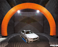
Figure 10 MVG’s SG3000F automotive test system.
The plane wave synthesizer (PWS) array or plane wave generator (PWG) array is an array of elements with suitably optimized complex coefficients, generating a plane wave in close proximity to the array. The PWG can achieve far-field testing conditions in a quiet zone located in a region close to the array, similar to what is achieved in a CATR but at shorter distance making the system more compact and easier to use. The main features of the PWG systems from MVG are the ability to cover the entire bandwidth for 5G testing in a single system. MVG offers large systems that can accommodate entire base stations, even vehicles (see Figure 10).
National Instruments Solutions
Whenever engineers discuss OTA test solutions, RF chambers almost automatically appear as necessary components of the solution. For design characterization, validation, compliance and conformance tests, a proper RF chamber (anechoic, CATR or reverberation types) provides a quiet RF environment that ensures the design meets all performance and regulatory requirements with sufficient margin and repeatability. However, for volume production, traditional RF chambers can take much of the production floor space, disrupt material handling flows and multiply capital expenses.
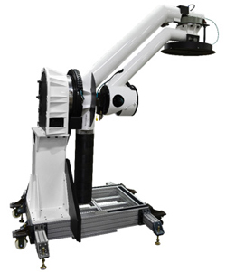
Figure 11 NSI-MI’s SNF-FIX-1.0 SNF System.
To tackle these problems, OTA-capable IC sockets - small RF enclosures with an integrated antenna - are becoming commercially available, enabling semiconductor OTA test functionality in a reduced form factor. Although the measurement antenna is a couple of centimeters away from the DUT IC, that is enough distance for far-field measurements for each individual antenna element. The relatively small size of the socket also facilitates multi-site, parallel tests to multiply test throughput, while minimizing signal power losses. On the other hand, the small socket prevents making beamformed measurements for the whole antenna array, which typically has a far-field distance of 10 cm or longer.
At 28 GHz, a 10 cm distance translates to over 20 dB of free space path loss, as opposed to just 1 dB on an equal length coax cable. Considering a receiver IP3 measurement, OTA methods would require the test instrument to produce 20 dB higher output power at the transmit antenna in order to achieve the same level of received power at the DUT. This can be a challenge for RF chamber-based OTA configurations; however, for OTA socket-based solutions, at 1.5 cm away, it only requires 5 dB higher transmitted power.
With the inclusion of active beamformer electronics, newer generation of 5G active antenna array devices now have many nonlinear RF components, such as digitally controlled PAs, LNAs, phase shifters and mixers. New designs incorporate multi-channel configurations in a single package. NI’s software-designed test platform keeps pace with the latest 5G NR PHY layer requirements and includes the measurement science and instantaneous bandwidth necessary to test wide NR component carriers or carrier-aggregated signals. NI’s high bandwidth instrumentation also allows for linearization of the DUTs using digital predistortion techniques. The NI platform provides for phase-coherent and time-aligned expansion into multi-channel measurement systems for comprehensive test coverage of the latest NR semiconductor devices.
NSI-MI Solutions
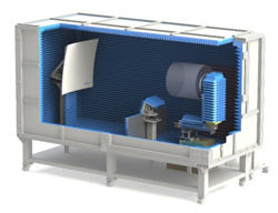
Figure 12 CAD drawing of NSI-MI’s portable CATR system with 80 cm quiet zone.
NSI-MI Technologies products for 5G testing include near-field and CATR systems. For near-field testing, NSI-MI recommends pattern testing only with CW tones when possible. The SNF-FIX-1.0 is a spherical near-field system that rotates a probe to any position on a sphere up to θ ≤ 150° around a stationary DUT. It does this with a dual rotary stage articulating arm. The advantage of this system is its ability to sample near-field patterns without the need for any type of rotation of the DUT. Figure 11shows the SNF test system. If DUT stationarity is not required, the SNF-RAZ-0.7 roll-over-azimuth system may also be used for SNF pattern testing.
For more general 5G testing, NSI-MI recommends a CATR. The chambers designed by NSI-MI can handle mmWave frequencies up to 110 GHz. The CATRs designed for 5G testing are intended for mmWave testing, as those frequencies are the primary driver for OTA testing in 5G. But they can be modified for FR1 OTA testing. They are designed for 30, 50, 80 and 100 cm quiet zones (see Figure 12).
Rohde & Schwarz Solutions
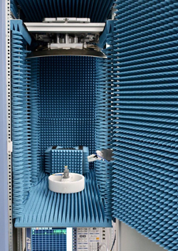
Figure 13 R&S ATS800R compact test chamber.
It is difficult to heat up or cool down an entire OTA chamber, more so since the absorber material used in these chambers cannot withstand very high or low temperatures. Neither can the motors in high accuracy positioners. The solution is the use of a relatively small enclosure around the DUT inside the chamber, changing the temperature only inside this enclosure rather than in the entire chamber. Of course, the enclosure itself must have only minimal influence on the radiation parameters or the beam emitted by the DUT.
A typical CATR setup is mounted inside a shielded chamber for RF conformance testing, typically together with a positioner. However, a chamber takes up space in a space limited R&D environment. R&S created a product where a CATR setup can be put on an engineer’s work bench or even inside a 19 in. rack taking up minimal floor space inside the lab, while providing a big and accurate quiet zone for RF and protocol R&D and regression testing (see Figure 13).
For testing antenna array systems, typically a chamber with 3D positioner is required to measure the 3D radiation pattern of the array under test. R&S offers the ATS1000 with a high precision conical cut positioner to fulfill these tasks in a very compact size (see Figure 14). As an additional option, the ATS1000 can be equipped with a “temperature bubble” in which extreme temperature conditions between −40°C and +85°C can be achieved using an external thermal stream. The bubble creates a relatively small closed environment around the DUT so the temperature changes can be achieved quickly. Since the bubble is made out of RF transparent material, the influence on the overall test results can be neglected.
Boonton, Noisecom Solution
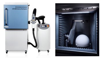
Figure 14 R&S ATS1000 test chamber.
The equipment and testing techniques used for engineering and quality assurance will be expensive and time consuming compared to what will be needed on the production line for 5G. Boonton, Noisecom has an interesting approach for OTA testing using a Noisecom calibrated noise source outside the chamber, connected to a transmit antenna inside the chamber. Receive antennas inside the chamber are connected to test equipment outside the chamber. The noise source can have one or two known excess noise ratio (ENR) values with calibration data for the bandwidth of interest. The benefit of having two ENR levels is the ability to determine Y factor noise figure of the DUT for radiated measurements.
An advantage of the noise source is the calibration points can normalize the equipment for power and frequency response. Once the equipment is normalized, the noise source is used to determine and verify the path loss of the interconnects in the system. Since the noise source is generating wide bandwidth OFDM-like signals, with crest factors (CF) similar to those to and from the DUT, it is straightforward to verify the system response to see if anything has changed between tests, perhaps caused by connector wear or operator error.
Boonton RTP5000 RF broadband RF power sensors can be connected to multiple receive antennas inside the chamber around the DUT (see Figure 15). The RF peak power sensors are capable of measuring the average and peak power being transmitted from the DUT. RF sensors can be synchronized to obtain composite average and peak power and determine CF. CF measurements are a quick figure of merit in a production test environment.
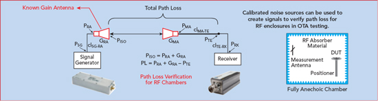
Figure 15 Boonton, Noisecom’s OTA path loss measurement using noise.
Noisecom noise sources are proven OFDM-like signal generators at a fraction of the cost of expensive signal generators and can be used for verification, calibration and signal source to speed up production tests. Boonton RTP5000 series RF peak power sensors offer a simple and fast way to measure complex OFDM signals using CF as a figure of merit to develop go, no-go testing.
SUMMARY
5G OTA testing will evolve quickly in 2019, as standards are defined and 5G products go into production. There will certainly be several methods needed to test and verify 5G components and systems, as noted in this article. The primary tradeoffs for cost, accuracy and throughput will need to be determined quickly and the test methods standardized as 5G deployments accelerate.