
A plethora of information discussing skew-matched data cables, such as Ethernet, is available for signal integrity applications. Data cables carrying differential signals over multiple internal wires necessarily have key parameters such as skew - any delay offset between the propagating signals means signal distortion and a perceptible loss of quality. In contrast, there is a noticeable lack of information about skew-matched coaxial cables and considerations for their respective application. This article discusses skew and applications for skew-matched coaxial cables.
Skew for data cables is typically defined as the difference in propagation delay or time delay between a differential pair cable assembly with the least delay and the differential pair with the most delay. Similarly, skew is inherent to individual pairs and is due to differences in conductor length or the velocity of propagation (VOP) of the individual conductors. VOP is defined as the speed at which a signal propagates through a path and is often expressed as a percentage of the free space value of the speed of light. While this definition sheds light on skew-matched high frequency cable counterparts, it does not take into account phase instabilities that can cause minor shifts in skew for coaxial assemblies.
Often, time delay is equated to group delay; while they are related, they are not identical. Group delay is the derivative of phase versus frequency. For some, group delay is more intuitive, as it can be roughly equated to the time for a pulse to arrive at a receiver or a rough estimation of the transmit time of a signal through a path. Group delay flatness, a measure of the variation in the group delay, is an important measurement in some systems, as it makes clear any abrupt changes in delay at the output of the device under test.
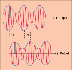
Figure 1 Group delay (τg) vs. phase delay (τp) of a modulated signal.
Not the same as group delay, time delay can be more accurately measured with phase delay (see Figure 1). For a signal propagating as a sine wave with an amplitude envelope, the group delay is analogous to the time delay of the amplitude envelope (τg in the figure), while the phase delay is the amount of time delay for each frequency component of the signal (τp). A coaxial pair with high delay accuracy needs the wave patterns to match at the output, as well as matching each frequency component.
Group delay is a helpful measurement for dispersive media such as a waveguide, where several modes can exist simultaneously. It is not particularly helpful for non-dispersive media, such as TEM-mode coaxial cable, as non-dispersive media remain pretty consistent across the bandwidth. Phase delay, however, can vary, as it is the integral of group delay with respect to frequency. For an ideal coaxial cable, group delay is not a function of frequency. It is constant.
Phase is a linear function of frequency, shown by the equation
![]()
where τ is the time delay. The time delay of a coax cable is directly proportional to the mechanical length and permittivity of the dielectric, shown by the equation

where LMECH is the mechanical length of the cable, ε is the relative permittivity of the dielectric material and c is the velocity of light. Phase stable coaxial cables depend on matched electrical lengths of their transmission lines, where the electrical length is related to the mechanical length by
![]()
This equation takes into account the permittivity of the dielectric material and, therefore, the effective phase length the signal must travel through the dielectric material. In addition to physical length, changes in the electrical length can occur through temperature variations, frequency and mechanical stress (e.g., flexing, vibration). Phase stable coaxial cables are typically produced using extensive temperature conditioning or specialized dielectrics. These cables are particularly important in systems using multiple coax lines to feed signals from a common source or to collect signals from scattered sources. A good example is a phased array system, where intentional phase shifts are used to create constructive and destructive signal interference.
Skew takes into account two or more signal paths and is defined as the difference in time delay (also known as propagation delay) between the signal paths. Skew matching a pair of coaxial cables involves phase matching them to control the time delay. It is important for skew-matched cables to be phase stable to reliability and maintain low skew despite flexure and temperature variation. Typically, the skew between a coax pair is proportional to the channel-to-channel delay match, often measured in picoseconds. The VOP is also a value measured in cables and, ideally, will be consistent between two cables, whether or not the cables have a matching physical length or phase angle.
Skew-Matched Coaxial Cable Construction
Figure 2 To minimize skew, matched coax cable assemblies should be constructed of the same materials and have the same mechanical orientation in use.
As stated earlier, delay-matched coaxial cables, by nature, must be phase matched and are individually phase stable to consistently maintain a delay match on the order of picoseconds (ps), despite frequency, temperature or flexure. Phase changes during flexure cannot entirely be eliminated due to the change in cross-sectional area - the bend radius of the outer region is larger than the inner conductor. These minute inconsistencies in inner geometry change the electrical length. As shown by the previous equations, the time delay is directly proportional to mechanical length and the dielectric constant, so a phase stable coax necessarily has both mechanical and temperature stability. Extreme flexibility in both the shielding and dielectric are needed to maintain mechanical stability despite flexure. Seemingly benign solutions such as a cable restraint can prevent cable flexure from causing inconsistent changes in electrical length and larger than expected delays (see Figure 2).
Changes in electrical length will inevitably occur due to the inner and outer conductor coefficients of thermal expansion, which indicates the growth or shrinkage of a material versus temperature. The metallic materials used for the inner conductor and shielding will grow and contract with temperature, causing a change in electrical length. This is often offset with dielectric cores such as expanded (microporous) polytetrafluoroethylene (ePTFE), where the dielectric constant decreases with an increase in temperature. This limits the change in phase that occurs with changing temperature. For these subtle reasons, simply purchasing two off-the-shelf coaxial cables of the same physical length and materials does not necessarily offer high delay match accuracies below 5 ps. The materials may not be phase stable, and the physical lengths may not be “identical.” A 1 mm difference between cable lengths with an identical VOP of 74 percent equates to almost 5 ps difference in propagation delay between two lines, as shown by

Given this sensitivity, the electrical delay of the coaxial cables is not only a function of the cut of the transmission line, also the precision with which the connectors are attached.
Why Picosecond Accuracies
Parallel bus architectures have been sufficient for transferring data at medium data rates. These topologies, however, become far less economical when transferring greater data rates, i.e., Gbps, as designers have to add signal lines or increase clock frequency. Increasing the width of the parallel bus or adding lines increases the size of the system: I/O cells, pins and their respective interconnections. Increasing the clock frequency is not feasible, as all transmitted data needs to arrive at the receiver simultaneously. While this can be accomplished over short distances, crosstalk, inductive and capacitive noise coupling, and parallel data skew become unmanageable as the distance increases. Because of this, high speed serial buses using serializer/deserializer (SerDes) circuits are typically implemented for VLSI/LSI applications. In practice, it is simpler to synchronize one clock to the transmitted data versus synchronizing multiple lines of data.
Thus, it is critical to synchronize the serial data stream with the clock, known as clock and data recovery. The pulse waveform at the output of the differential receiver needs to maintain the high timing resolution of the original pulse signal, aligned with the rising and falling edges of the waveform. In any system, there is always inherent jitter contributed from the transmitter, making it increasingly important to discern jitter from the PCB or link (i.e., cable).
Embedded clocks have a frequency inversely proportional to the unit interval (UI), defined as the time duration of a pulse and measured in picoseconds. Eye diagrams are a useful tool for understanding the jitter of a differential signal, as the eye displays waveforms from multiple UIs, with either the embedded clock or a reconstructed one. As digital logic advances to support increasing switching rates, UIs become smaller. For example, a 12.5 Gbps clock frequency corresponds to an 80 ps UI (or bit length), and a 50 Gbps clock frequency corresponds to a 20 ps UI. Relevant performance metrics such as jitter can be difficult to discern in a test system with a relatively high differential skew. This is especially true in high data rate applications where the misalignment of rise and fall times generates a much less open eye. Electromagnetic analysis over wider bandwidths becomes important, as equipment such as oscilloscopes usually needs to capture up to the fifth harmonic to accurately reconstruct signals in the time domain. For a data link running at 28 Gbps, the analysis requires a bandwidth from DC to between 40 and 50 GHz. As CMOS technology evolves to support faster switching, it becomes increasingly important to minimize skew to enable testing over wider bandwidths without additional data-dependent jitter.
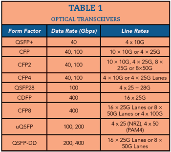
With Ethernet, current iterations of 40G and higher do not include a SerDes function; they use parallel, multi-lane architectures. The alignment of the parallel channels is accomplished through a striping function. The receiver physical coding sublayer performs skew compensation with alignment markers to reassemble 40G and higher aggregate datastreams. In theory, any lane can be used for clock recovery. As shown in Table 1, optical transceivers for 40G, 100G and 400G contain four to 16 lanes, each offering 10 to 50 Gbps speeds. A minor offset in synchronicity between each lane can ultimately reduce waveform quality, making it increasingly necessary to measure parameters such as bit error rate and jitter with multichannel test equipment and obtain transmission media that adds minimal skew.
Conclusion
The increased use of differential signal communication calls for reliable, delay-matched transmission lines with less than 1 ps skew. When coaxial assemblies are used as the medium, the cables must be very close to the same physical length and constructed of the same materials to ensure tight skew accuracy. Skew in a test system can limit the reception of a differential signal, adding deterministic jitter such as data-dependent jitter and causing errors in the received data.