
LATEST COTS SDR TECHNOLOGY
Hardware
Over the past 10 years, FPGA manufactures like Xilinx have been improving technology by reducing the size of silicon process nodes, which reduces device size, weight and power (SWaP). In late 2008, the Xilinx Virtex-6 family was constructed using a 40 nm process and averaged 2000 DSP slices per FPGA. By 2017, the Ultrascale family was on a 20 nm process, and the FPGA DSP slices increased to approximately 5,500. The latest system on a chip (SoC) from Xilinx, the RFSoC, consists of an FPGA fabric with ARM processors, ADCs and DACs, all on the same chip. The 16 nm technology has over 4,200 DSP slices; four 1.5 GHz, A53 ARM processors; two 600 MHz, R5 ARM processors; eight 4 GHz, 12-bit ADCs; and eight 6.4 GHz, 14-bit DACs per device.
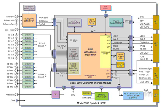
Figure 3 Pentek COTS SDR based on the Xilinx RFSoC.
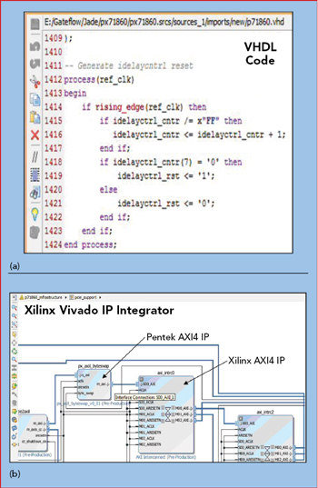
Figure 4 Xilinx IP Integrator tool, showing VHDL code (a) and intuitive “drag and drop” graphical blocks (b).
Figure 3 shows a functional block diagram of one COTS implementation of the Xilinx RFSoC, the central component of the 5950 3U VPX board from Pentek. The center area including the RFSoC is a fully connectorized system on module (SoM) that plugs into a 3U VPX carrier. While this device can be controlled via a Gigabit Ethernet port, similar to the previous generation FPGA, the on-board ARM processors allow autonomous operation and the ability to communicate with, or control, devices locally or on an external network.3
Firmware
Previous generation FPGAs were programmed using a textual hardware description language (HDL) like VeriLog or very high speed integrated circuit description language (VHDL). The latest AXI4 compliant IP blocks are included in Vivado from Xilinx. The IP Integrator tool from Xilinx has virtual graphical blocks that represent HDL code, which can be connected to one another via drag-and-drop wiring. Figure 4 shows an example of VHDL code (see Figure 4a) and the corresponding drag-and-drop graphical blocks (see Figure 4b). This more intuitive way to program allows someone new to FPGAs to wire together logical blocks representing hardware like FIR filters and DDCs to create an SDR. This programming method supports fast integration of vendor-supplied, hardware-specific IP blocks with Xilinx IP blocks to create a working SDR. Both IP block types can be combined to create a common library.
Software
These IP programming advances have provided an opportunity for COTS vendors to create a single BSP module that corresponds to one IP module with all the necessary FPGA program parameters in one location. One example is a “clock control BSP module” that corresponds directly to a “clock control IP module.”
5G APPLICATION
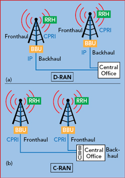
Figure 5 Distributed (a) and centralized (b) RAN.
This latest generation of SDR technology is game changing and can be used by COTS manufacturers to provide multi-channel SDR transceivers for engineers developing 5G radio products.
Figure 5 illustrates the difference between distributed and centralized radio access networks, D-RAN and C-RAN. With LTE, the traditional D-RAN cell sites were being replaced by newer C-RANs to improve data transfer efficiency and reduce radio cost. However, the mmWave massive MIMO architecture for 5G requires the separation to move the remote radio head (RRH) closer to the end user because of the increased RF path loss.
Figure 6 shows a functional block diagram of a C-RAN consisting of a baseband unit (BBU), RRH, GPS time/frequency reference and an interconnect module. Several of the blocks are highlighted to note possible use of COTS SDRs. The BBU is located at a central office or a virtual network “in the cloud,” with access to multiple optical data lines for backhaul. The RRH is at an external location closer to the end user. The BBU and RRH in this fronthaul connection example can use a common public radio interface (CPRI), open base station architecture initiative (OBSAI) or standard Ethernet connection, depending upon system requirements. New fronthaul concepts like extensible radio access networks (xRAN) and open radio access networks (ORAN) will replace these legacy interfaces in the future.
These various transfer mode options combined with legacy cellular, Verizon 5G Technical Forum (5GTF) or the 3GPP 5G New Radio (NR) specification are configured to form a complex heterogeneous network, requiring a flexible development platform.4-6
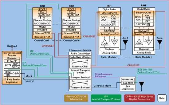
Figure 6 C-RAN functional block diagram, showing where COTS SDR can be used.
Hardware
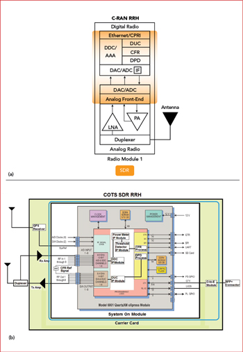
Figure 7 RRH functional block diagram (a), showing the functions that can be implemented with a COTS SDR (b).
Figure 7 shows an example of using a COTS SDR board to emulate a RRH in a C-RAN architecture. A subsection of the original C-RAN with the RRH is shown in Figure 7a, with the COTS SDR RRH in Figure 7b. The encircled area in Figure 7a can be realized with the carrier card shown in Figure 7b. The custom modular carrier card contains the receive and transmit amplifiers, a GPS receiver and an optoelectronic transceiver module. The inner SoM contains the RFSoC and all connections for power management, data storage and analog/digital I/O. The incoming RF signal from the antenna is connected to the receive low noise amplifier via a duplexer, isolating it from the high power amplifier transmit levels and connecting it to one ADC channel. With the necessary IP, this SoM and custom carrier combination can emulate the original RRH.
Firmware
Once inside the FPGA fabric, the digital samples are decimated, frequency selected or tuned and filtered in the DDC. The DDC output samples can be streamed to the power meter module for measurement and sorted in the threshold detector IP module. These processed samples can be streamed to the ARM processors for crest factor reduction and digital predistortion routines before being up-converted in the digital up-converter (DUC) for re-transmission. The DUC is the reverse of the DDC, using frequency translation and interpolation instead of decimation. The digitized I/Q sample data is packetized in the digital radio for transport to the BBU via a radio data switch. Because of the variety of channels and data transfer protocols, it is necessary to understand the maximum data throughput of the signal and ensure sufficient network capacity (see Sidebar Data Transport Requirements).
Software
Depending on the desired level of control, BSP routines would be created for the new IP and ARM processors, or the ARM processors, in conjunction with the FPGA, can be programmed to operate autonomously.
CONCLUSION
The purpose of this article is to familiarize a traditional radio engineer with the latest hardware, firmware, software and design tools available from COTS SDR suppliers, showing that an SDR can be used as a 5G development platform. These SDR platforms provide superior signal integrity, high test repeatability and modular assemblies that adjust to constantly changing 5G design requirements. 5G evolution will require many development cycles for experimentation and optimization, and the use of a COTS system as a starting point will accelerate time to market.
References
- R. Hosking, “Putting FPGA’s to Work in Software Radio Systems,” 11th Edition, Pentek, March 2018, www.mwee.com/Learning-center/pentek-putting-fpgas-work-software-radio-systems-11th-edition.
- W. Kester, “Taking the Mystery Out of the Infamous Formula ‘SNR = 6.02+1.76dB,’ and Why You Should Care,” Analog Devices, October 2008, www.analog.com/media/en/training-seminars/tutorials/MT-001.pdf.
- S. Sgandurra, “Strategies for Deploying Xilinx’s Zynq Ultrascale+ RFSoC,” Pentek, May 2018, www.pentek.com/pipeline/27_2/rfsoc.cfm.
- S. Ahmadi, “Towards 5G; Xilinx Solutions and Enablers for Next-Generation Wireless Systems,” XILINX, June 2016, www.xilinx.com/support/documentation/white_papers/wp476-toward-5g.pdf.
- A. Oliva, J. Hernandez, D. Larrabeti and A. Azcorra, University of Madrid (UC3M), An Overview of the CPRI Specification and Its Application to C-RAN-Based LTE Scenarios IEEE Communications Magazine, February 2016.
- P. Moakes, “5G New Radio Architecture and Challenges,” CommAgility White Paper.