
With the large number of LTE bands, wireless devices require many sophisticated multiband antenna designs.1-12 One of the biggest challenges with 4G-compared to 2G and 3G, which used only 824 to 960 and 1710 to 2170 MHz-is the large operating bandwidth: 698 to 960 and 1710 to 2690 MHz. The lower frequencies of the low frequency region, especially from 698 to 960 MHz, exacerbate the challenge, since the antennas must be small compared to the operating wavelength.
This article shows how combining a small antenna booster from Fractus Antennas-86.4 mm3-with a small antenna tuner from Cavendish Kinetics-just 2 mm2 in area-yields an antenna system that covers the LTE frequency bands within the 698 to 2690 MHz frequency range.
BOOSTERS + TUNERS
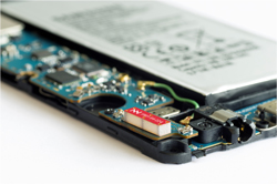
Figure 1 Antenna booster, measuring 12 mm x 3 mm x 2.4 mm, mounted on a corner of a smartphone PCB.
Virtual AntennaTM technology13-18 relies on very small antenna elements, called antenna boosters, which makes it a good approach to satisfying the bandwidth requirements of LTE. Using a matching network, the bands of operation are not adjusted by designing a complex antenna geometry, only a proper matching network, which is faster and more cost effective. The same antenna booster can operate with different platform sizes, since only the matching network changes from one design to another.18 This is a different approach than conventional antenna design, where the antenna geometry has to be designed case by case. Besides being small, antenna boosters are surface-mount components, simplifying their integration in wireless devices (see Figure 1).
Antenna tuners are precise, low loss, variable capacitors that tolerate high RF voltages, making them ideal for tunable antennas, dynamic load adjustments, tunable filters and analog RF applications that require high voltage operation. The Cavendish Kinetics antenna tuners use patented RF MEMS technology, which eliminates the high insertion loss and RF voltage handling limitations of traditional silicon on insulator (SOI) or GaAs devices in the RF front-end.
A design combining the Fractus Antennas antenna booster with a Cavendish Kinetics antenna tuner supports all the communication frequency bands within the 698 to 2690 MHz frequency range.19-20 The main benefit of such a booster-tuner combination: the wireless device can dynamically optimize the performance over a specific bandwidth within the entire frequency range, providing the maximum radiation for the platform to support every coverage and user operation scenario.
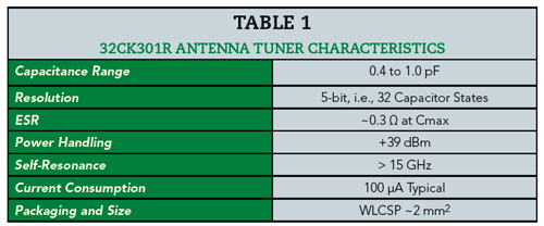
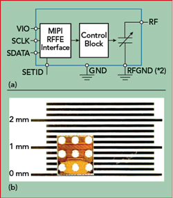
Figure 2 Antenna tuner block diagram (a) and photo (b), showing the tuner’s 1.4 mm x 1.4 mm size.
Cavendish Kinetics’ RF MEMS technology and manufacturing process produce devices with accuracy and reliability, maintaining full specification compliance even after 100 billion cycles.21-22 The 32CK301R SmarTune™ Antenna Tuner (see Table 1) was used to demonstrate the design concept in this article. Products with wider capacitor range are available, and the Cavendish Kinetics’ family of tuners offers various capacitance ranges between 0.4 and 3 pF. All SmarTune antenna tuners are controlled through a MIPI RFFE interface (see Figure 2), with the tuner’s functions self-contained and managed by the logic in the controller.
RECONFIGURABLE MATCHING NETWORK
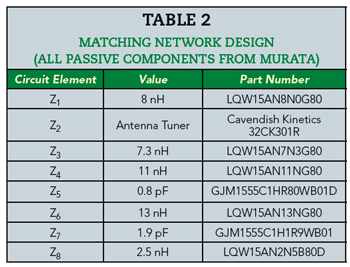
Referring to Figure 3, the proposed reconfigurable matching network comprises the MEMS shunt tunable capacitor (Z2) and seven lumped capacitors and inductors (see Table 2). In this design, all the passive components, from Murata, are SMD 0402 type and high Q with tight tolerances. The tunable capacitor has 32 states, digitally controlled, with each state corresponding to a capacitor value ranging from 0.4 to 1 pF. In this design, the values and states are 0.40 (S00), 0.44 (S02), 0.55 (S08) and 0.92 pF (S27).
The impedance of the antenna booster without the matching network is very poor, in particular at the low end, from 698 to 960 MHz, where the |S11| is worse than −1 dB.17 However, with the multiband matching network, the performance can easily be adjusted without changing the antenna geometry. The location of the antenna booster is important to excite efficient radiation modes of the ground plane. In this design, the corner of the ground plane was selected.16-17
The state of the tunable capacitor is software-controlled via a parallel interface connection at the end of the ground plane. The interface connects the evaluation board to a PC running Cavendish Kinetics’ SkyWalker software, which is used to set the impedance tuner to any of its 32 states.
Since the ground plane is an important contributor to the radiation, to avoid an undesirable effect from the interface connection when measuring antenna performance, the following procedure was used: The desired state of the impedance tuner was selected with the interface connection attached. After the state was set, the interface connection was removed, with a battery on the ground plane providing a DC voltage to the tuner to maintain the state. This enabled the antenna efficiency and S11 to be measured without any impact from the interface connection.
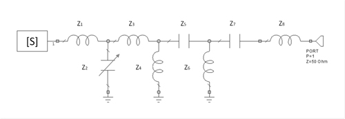
Figure 3 Reconfigurable matching network. Z2 is the variable capacitor from Cavendish-Kinetics.
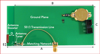
Figure 4 FR4 evaluation board showing the Fractus Antennas antenna booster, the Cavendish antenna tuner and the matching network.
Figure 4 shows the evaluation board, with the battery and 10-pin parallel interface connector on the right-hand side. A UFL cable connects the antenna booster to an SMA connector mounted on the edge of the board.
PERFORMANCE RESULTS
For each of the four states of the antenna tuner, the total efficiency (ηt) was measured inside an anechoic chamber with 3D pattern integration using Satimo Stargate-32 (see Figure 5). Total efficiency includes both the radiation efficiency (ηr) and mismatch losses, where ηt = ηr•(1 − |S11|2). Revieiwing the measured data, state S27 covers some of the LTE low bands, i.e., from 698 to 746 MHz, and state S08 is selected to cover 746 to 824 MHz.
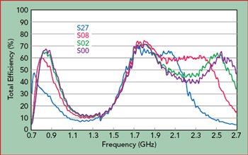
Figure 5 Measured efficiency for four states.
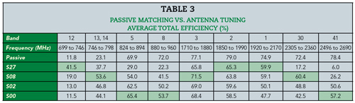
To assess the effectiveness of antenna tuning, the performance of a passive matching network designed to cover 698 to 960 and 1710 to 2690 MHz was compared with this active tuning design (see Table 3). The table confirms that the passive network does not cover all the LTE bands. The advantage of antenna tuning is remarkable in the low LTE bands, i.e., from 699 to 798 MHz. In band 12, the efficiency of the active solution is 5.4 dB better than the passive design and 3.6 dB better in bands 13 and 14. The efficiencies are comparable in the other bands, i.e., within 1.4 dB.
CARRIER AGGREGATION
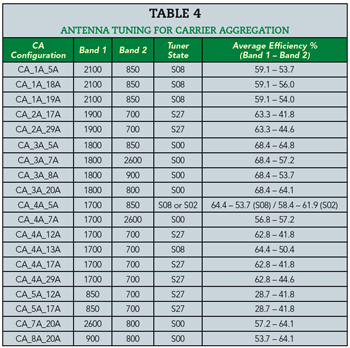
The evaluation board design is suitable for use with carrier aggregation (CA), where several LTE frequency bands are used simultaneously to increase the data rate. Table 4 shows the antenna tuner states recommended for each inter-band CA pair.
CONCLUSION
A small antenna booster of 86.4 mm3 mounted on a ground plane measuring 120 mm x 60 mm and a reconfigurable matching network demonstrated coverage of the cellular bands from 698 to 960 and 1710 to 2690 MHz. To achieve the highest possible performance, the reconfigurable matching network was designed using a MEMS tunable capacitor with passive components. The measured average total efficiency was above 40 percent, making this design approach feasible for most wireless and mobile devices.
ACKNOWLEDGMENT
This project was co-financed by the Spanish Ministry of Industry, Energy, and Tourism under the National Plan of Scientific Research, Development and Technology Innovation 2015-2017 (Project Ref: TSI-100103-2015-39).
References
- J. Anguera, A. Andújar, M. C. Huynh, C. Orlenius, C. Picher and C. Puente, “Advances in Antenna Technology for Wireless Handheld Devices,” International Journal on Antennas and Propagation, Vol. 2013, Article ID 838364.
- J. Ilvonen, R. Valkonen, J. Holopainen and V. Viikari, “Design Strategy for 4G Handset Antennas and a Multiband Hybrid Antenna,” IEEE Transactions on Antennas and Propagation, Vol. 62, No. 4, April 2014, pp. 1918–1927.
- J. Lee, Y. Liu and H. Kim, “Mobile Antenna Using Multi-Resonance Feed Structure for Wideband Operation,” IEEE Transaction on Antennas and Propagation, Vol. 62, No. 11, November 2014, pp. 5851–5855.
- H. Xu et al., “A Compact and Low-Profile Loop Antenna with Six Resonant Modes for LTE Smartphone,” IEEE Transactions on Antennas and Propagation, Vol. 64, No. 9, September 2016, pp. 3743–3751.
- K. L. Wong, “Planar Antennas for Wireless Communications,” Wiley Inter-Science, 2003.
- R. Aziz, A. Arya and S. O. Park, “Multiband Full Metal Rimmed Antenna Design for Smartphones,” IEEE Antennas and Wireless Propagation Letters, Vol.15, March 2016, pp.1987–1990.
- C. W. Yang, Y. B. Jung and C. W. Jung, “Octaband Internal Antenna for 4G Mobile Handset,” IEEE Antennas and Wireless Propagation Letters, Vol. 10, 2011, pp. 817–819.
- Y. Liu, Y. Luo and S. Gong, “An Antenna With a Stair-Like Ground Branch for Octa-Band Narrow-Frame Mobile Phone,” IEEE Antennas and Wireless Propagation Letters, Vol. 17, No. 8, August 2018, pp. 1542–1546.
- A. Lehtovuori, R. Valkonen, J. Ryynänen and M. Valtonen, “Design Equations for Dual Wideband Matching of Capacitive Coupling Element Antennas,” Microwave and Optical Technology Letters, Vol. 56, 2014, pp. 236–240.
- R. Valkonen, M. Kaltiokallio and C. Icheln, “Capacitive Coupling Element Antennas for Multi-Standard Mobile Handsets,” IEEE Transactions on Antennas and Propagation, Vol. 61, No. 5, May 2013, pp. 2783–2791.
- R. Valkonen, J. Ilvonen, C. Icheln and P. Vainikainen, “Inherently Non-Resonant Multi-Band Mobile Terminal Antenna,” Electronics Letters, Vol. 49, No. 1, January 2013, pp. 11–13.
- Y. Wang and Z. Du, “Wideband Monopole Antenna With Less Nonground Portion for Octa-Band WWAN/LTE Mobile Phones,” IEEE Transactions on Antennas and Propagation, Vol. 64, No. 1, January 2016, pp. 383–388.
- J. Anguera, A. Andújar, C. Puente and J. Mumbrú, “Antennaless Wireless Device Capable of Operation in Multiple Frequency Regions,” Patent Application WO2010/015364, July 2009.
- A. Andújar, J. Anguera and C. Puente, “Ground Plane Boosters as a Compact Antenna Technology for Wireless Handheld Devices,” IEEE Trransactions on Antennas and Propagation, Vol. 59, No. 5, May 2011, pp. 1668–1677.
- J. Anguera, N. Toporcer and A. Andújar, “Slim Radiating Systems For Electronic Devices,” Patent Application WO2016/012507.
- J. Anguera, C. Picher, A. Bujalance and A. Andújar, “Ground Plane Booster Antenna Technology for Smartphones and Tablets,” Microwave and Optical Technology Letters, Vol. 58, No. 6, June 2016, pp.1289–1294.
- A. Andújar, J. Anguera and R. Mateos, “Multiband Non-Resonant Antenna System with Reduced Ground Clearance,” European Conference on Antennas and Propagation, April 2017.
- J. Anguera, A. Andújar and C. Puente, “Antenna-Less Wireless: A Marriage Between Antenna and Microwave Engineering,” Microwave Journal, Vol. 60, No. 10, October 2017, pp. 22–36.
- J. Anguera and A. Andújar, “Wireless Device,” Patent Application U.S. 2017/0202058, January 2016.
- J. Anguera, A. Andújar, J. L. Leiva, C. Schepens, R. Gaddi and S. Kahng, “Multiband Antenna Operation with a Non-Resonant Element Using a Reconfigurable Matching Network,” European Conference on Antennas and Propagation, April 2018.
- V. Joshi et al., “MEMS Solutions in RF Applications,” IEEE SOI-3D-Subthreshold Microelectronics Technology Unified Conference, October 2013.
- R. Gaddi et al., “Measurement-Based Optimization of Aperture Tunable Antennas,” Microwave Journal, Vol. 60 No. 10, October 2017, pp. 72–84.