
With the increase in the number of connected devices and the attendant appetite for sending and receiving data, the demands on cellular networks are increasing. To help address this trend, device and antenna designers are tasked to develop better systems on the client side to improve network performance. Among the options, designers can employ dynamic communication link optimization using software antenna techniques, which provides more capability to the radio architecture and antenna systems. This enables companies to develop more compact and cost-effective radio systems while supporting wider bandwidth and multiple modulation schemes. A number of military and commercial applications for software-defined radios (SDR) benefit from software-defined antennas (SDA), and these benefits can be extended to the multitude of mission-critical applications in IoT, such as controls for railroads, underground gas leak detection and forest fire prevention.
This article outlines the technical approach and benefits provided by SDAs, capabilities that enable antennas to go well beyond the performance of passive antennas, dynamically tracking signals in mobile applications and keeping the communication link optimized.
SOFTWARE-DEFINED ANTENNAS
Companies developing mission-critical systems, where reliable connectivity or high data rates need to be sustained, rely on flexibility in the radio architecture and antenna system to allow for dynamically optimizing the communication link. This optimization can be provided by SDAs, which support the radio system accessing wider frequency ranges and using flexible modulation to maintain and improve performance.
With the number of M2M and IoT devices far surpassing the population of smartphones around the world, cellular signal congestion and interference become major concerns. As more devices get connected to existing networks, the response is to increase the number of base stations or nodes, which exacerbates the interference problem. Today’s passive antenna systems used in cellular client devices for metering, vehicle tracking and industrial automation lack the dynamic beamwidth control and front-to-back ratio available from large array antennas. Adopting SDA techniques will provide beamwidth and angular discrimination to minimize interference in node-based cellular networks, both 4G and 5G.
During the last decade, SDAs have become feasible due to innovations on two fronts: RF tuning components and RF modem chipsets. A wide variety of RF tuning components and manufacturing techniques for these components have matured, with available components comprising switches, tunable capacitors, RF MEMS switches and tunable capacitors, BST tunable capacitors and PIN diodes. Modem chipsets provide metrics for real-time dynamic optimization at moderate to low latency, such as signal-to-interference-and-noise ratio (SINR) and channel quality indicator (CQI). Such metrics can be used to decide the optimal tuning state of the antenna system.
PASSIVE ANTENNA LIMITATIONS
In a communications link, the antenna radiates and receives electromagnetic energy. An antenna a few tenths of a wavelength in size can be used to radiate energy over a broad angular region, approaching the performance of the theoretical isotropic radiator, i.e., radiating equally in all directions. Radiation over broad angular regions is important for mobile communications, due to the multipath environment, time-varying changes in the multipath environment and the mobility of the client device - all causing dynamic variations in the propagation channel. Ideally, the passive antenna in the client device should radiate in all directions, since the direction to the base station antenna is unknown, and multipath causes the radiated signals to and from the base station to scatter and reflect over a wide angle.
An electrically larger antenna, one that is one to several wavelengths in size, can be designed to radiate over a more restrictive angular range. A reduced 3 dB beamwidth between 30 and 80 degrees focuses more of the radiated energy in the desired direction and provides several dB of improved antenna system gain, which translates to higher data rates. This reduced beamwidth radiation pattern also provides better rejection of interfering signals arriving from directions outside the main beam of the antenna. However, a more directive and efficient antenna needs to be pointed in the correct direction for optimal link margin with the intended base station, meaning more information is needed to implement this type of antenna with mobility and non-line-of-sight conditions.
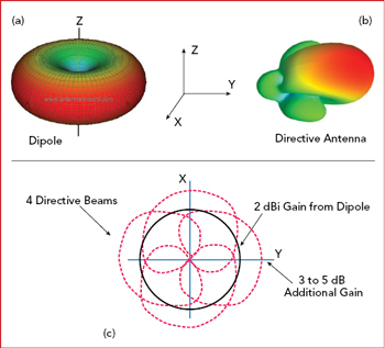
Figure 1 Comparison of the radiation patterns of a dipole (a) and more directive (b) antenna, showing the directive antenna provides higher gain (c).
Figure 1 compares the radiation patterns of a dipole antenna and a more directional antenna, which provides more gain. The dipole pattern (see Figure 1a) has omnidirectional coverage in the x-y plane and two deep nulls in the z direction, while the more directive antenna (see Figure 1b) has reduced beamwidth in both the x-y plane and z direction; however, it provides increased gain in the direction of the main lobe. Overlaying the dipole radiation pattern in the omnidirectional plane with the radiation patterns of the more directional antenna (see Figure 1c) shows the increase in gain with the directive antenna. Its beam can be dynamically steered to cover four 90 degree quadrants and provide 360 degree coverage.
Figure 1 shows the benefits of dynamic beam steering afforded by a SDA, comparing the low directivity, wide beamwidth, passive antenna to the multiple beams generated by a beam steering antenna. Taking the multiple beams to form a composite radiation pattern, the best case benefit is achieved when beam steering is coupled with an algorithm calculating the radio link metrics and using this data to select the optimal beam. When low latency metrics are available from the radio baseband chipset to drive the optimization process, a well-configured algorithm allows for 80 to 90 percent of the composite pattern benefit to be achieved.
SOFTWARE-DEFINED ANTENNA EXAMPLE
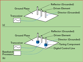
Figure 2 Passive Yagi antenna on a ground plane (a). Same antenna with dynamic tuning (b).
As discussed, a SDA is dynamically reconfigured in real-time to compensate for changes in the propagation channel and to accommodate changes in the radio system. To design a SDA to provide hemispheric or full 3D coverage, a couple of configurations can be used: either a centralized antenna element with parasitic elements on the periphery or the inverse, where multiple antenna elements surround a central parasitic element. The first is easier and more efficient to implement, since there is only one driven antenna element; the second configuration requires multiple antenna elements surrounding a single parasitic element, and these multiple antenna elements need to be switched to change the radiation pattern. Switch cost and losses make this configuration less efficient than using a single antenna with multiple parasitic elements.
In either case, active tuning components are integrated into the antenna element or parasitic elements to provide switching or tuning. An RF switch can be used to connect or disconnect portions of a conductor that is part of a parasitic element or section of the driven antenna; this change in conductor configuration alters the current distribution of the parasitic element or the driven antenna. Alternately, a tunable capacitor can be used at the junction of two conductors, introducing a dynamically-varied capacitance for impedance loading and connecting discrete conductors.
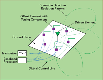
Figure 3 More complex SDA, where the beam is steered to different sectors.
One example of a passive antenna (see Figure 2) is a Yagi on a ground plane, which provides a directive radiation pattern in one direction. By adding tuning components to the reflector and director elements, the elements can by dynamically connected or disconnected from the ground plane. When the reflector and director are connected or “grounded” to the ground plane, the radiation pattern will be directive, with the peak gain pointing in one direction. When the reflector and director are disconnected, the radiation pattern reverts to that of a monopole on a ground plane, with an omnidirectional pattern in the plane of the ground plane. The gain of the Yagi on a ground plane is 5 to 6 dB greater than that of a monopole.
Figure 3 shows a more complex version of a SDA system, where multiple elements with tuning components are located around a centrally-driven antenna element. As the various tuning components are activated, to connect or disconnect the element to the ground plane, a directive radiation pattern is generated and rotated in the plane of the ground plane, steering the direction of the peak gain of the antenna. A combination of the centrally-driven antenna and one of the offset elements with tuning components is a type of Yagi antenna, shown in Figure 2b.
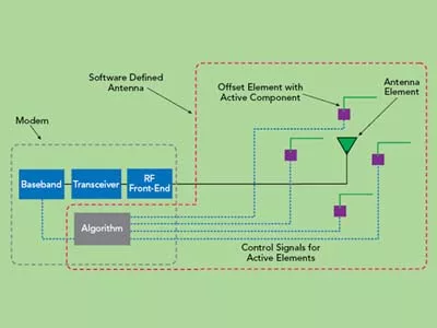
To complete a SDA system, an algorithm is required that uses metrics from the baseband chipset of the radio to determine optimal beam selection. Figure 4 shows a radio modem and SDA, controlled with the algorithm. The algorithm ties the modem and SDA together; this is highlighted in Figure 4, where the dotted lines that define the modem and SDA overlap at the algorithm.
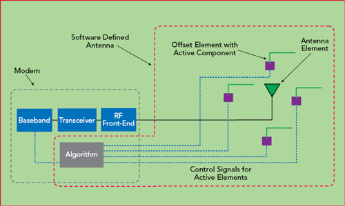
Figure 4 SDA driven by the radio modem.
This discussion of the antenna system architecture only refers to a single port antenna, with two antennas needed for a 2 × 2 LTE MIMO application.
SYSTEM-LEVEL BENEFITS
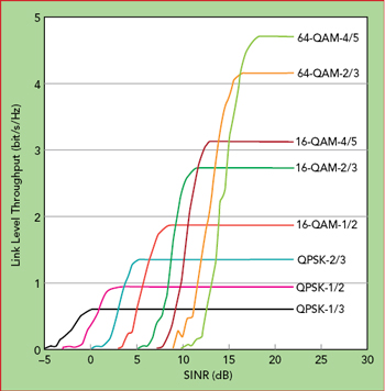
Figure 5 Link data throughput vs. SINR.1
A SDA with beam steering can provide from 3 to more than 6 dB of additional antenna gain. The additional gain equates to the same level of system gain, resulting in higher data rates. Figure 5 shows the relationship between data throughput and SINR. A measure of the signal level above the level of noise and interfering signals, the SINR will increase on a dB per dB basis as the antenna system gain is improved. Figure 5 shows the benefits of additional antenna system improvement on system metrics, such as throughput.
With low SINR values, an LTE network will use quadrature phase-shift keying (QPSK), essentially the same as 4-QAM. As the QAM index increases, the data rate increases and the SINR needed to support the modulation increases. When the SINR exceeds 7 dB, 16-QAM, which has 2× the throughput of QPSK, can be used for transmission. With an SINR of 13 dB, the best modulation becomes 64-QAM, which has 2× the throughput of 16-QAM and 4× the throughput of QPSK. Antenna system improvements obtained from a SDA will be most noticeable at lower SINR.
With the widespread adoption of smartphones and the evolution of cellular networks to 5G, the approach for the antennas in the client device has been to design a low directivity, omnidirectional antenna-or as close to omni as possible-to ensure the client is capable of receiving signals across the widest spherical geometry. Since a device with a passive antenna has no understanding of base station location or the angle of arrival, this wide beamwidth approach provides the best method for making the system work, accounting for mobility and the change in orientation and position of the device within the cell. Unfortunately, from a system link budget perspective, this does not efficiently transmit the power from the antennas in the client device, since the power is radiated in all directions, despite the intended direction of the radiated signal to the base station hosting the link. When receiving, the passive, wide beamwidth antenna has a peak gain lower than a more directive antenna. A directive antenna could be used if the antenna “knew” which direction to point.
SUMMARY
The SDA system can add multiple dBs of system-level benefits when dynamic optimization of the radiating element is incorporated with signaling from the baseband modem, with an algorithm to optimize the antenna. Besides providing more gain in the intended direction, a SDA will reduce interfering signals arriving from directions other than the intended base station. The underlying principle is the relationship between gain and beamwidth of an antenna: generating higher peak gain in the radiation pattern, other angular regions will be illuminated less, i.e., lower gain in directions outside of the main lobe of the radiation pattern.
If an SINR metric is available from the baseband modem chipset with an algorithm to optimize the SDA, the interference in the propagation channel will be considered as the radiation pattern characteristics are surveyed and optimized. This is becoming more important as base stations are more densely deployed to meet capacity demands. As the base station density increases, interference becomes the more limiting factor for throughput, rather than signal strength.
Today’s antenna engineer can take advantage of the evolving features in radio modems, such as low latency SINR metrics and tunable component technology, to reconfigure passive antennas to dynamically optimized SDA systems. If radiation patterns are chosen for dynamic optimization, sectorization will provide 3 to 6 dB of system-level improvement compared to a low directivity passive antenna. Optimizing the pattern will become more important as cellular networks increase the density of base stations, enabling the link to be optimized for both signal levels and interference in the propagation channel.n
Reference
- J. J. O. Bonafé, A. S. Pagès, S. R. Boqué, M. Garcia-Lozano and D. Gonzalez Gonzalez, “Link Level Simulator for LTE Downlink,” 2009, www.researchgate.net/publication/47330409_Link_level_simulator_for_LTE_downlink.