
The operating principle and design of compact, non-standard, reduced height waveguide planar magic tee junctions are described. The distinguishing feature of these components is the placement of the difference port on a layer separated from other three ports by a common waveguide broadwall. The two parts of the component are coupled through a slot located in the common broadwall of two. A design methodology making use of extensive electromagnetic modelling based on method of moment (MoM) analysis and finite element method (FEM)-based commercial software has been developed. The use of such planar magic tee junctions in developing planar monopulse comparators for airborne slotted array applications has been demonstrated.
The workhorse of most tactical aircraft and missile systems deployed in the field today, as well as a number of non-military applications, is the mechanically scanned monopulse slotted waveguide array antenna because of its rugged and compact structure, high radiation efficiency, precise control over amplitude and phase, and high power handling capacity.14 These arrays use a multilayer feeding structure with two plane monopulse comparator networks to get the required monopulse capability. The weight, size and profile (compactness) of the slotted array antenna depends on the individual modules of the array like radiating and coupling waveguides, feeder networks and monopulse comparator networks. The monopulse comparator network forms a critical part of an antenna system. This network extracts power from the four quadrants of the antenna to give a sum pattern and two orthogonal difference patterns. Any error in the network can severely affect the performance of the complete antenna. A magic tee, being the basic building block of a monopulse comparator, plays a very important role in making such arrays lightweight and compact. The performance of a monopulse comparator depends on the accuracy with which individual magic tees are designed. Due to the compact nature of the slotted waveguide structure it is required to design compact folded magic tees. Also, care should be taken in the design to see the viability of mass producing these comparators as an integral part of the antenna.
In this article, the designs of two different types of compact planar magic tee junctions -- a planar magic tee junction (PMTJ1) using a collinear transverse waveguide slot coupler and a planar magic tee junction (PMTJ2) with a longitudinal/transverse slot coupled difference port -- have been accomplished based on MoM analysis and FEM-based CAD high frequency structure simulator software (HFSS).5 The scattering matrices of these magic tee junctions which have been used to design a compact two plane monopulse comparator are explained, along with experimentally evaluated results.
DESIGN CONCEPT
Two design concepts using a hybrid waveguide junction incorporating an aperture interconnection between two layers are demonstrated. The geometries of PMTJ1 and PMTJ2 are shown in Figure 1. These are two layer structures consisting of an H-plane waveguide tee junction coupled through a slot to another waveguide lying underneath and parallel or perpendicular to the main arm of the H-plane tee junction. The slot is located in the common broadwall of the two waveguides. The lower waveguide (shown in dotted line) is fed from one end (port 1) and short-circuited at the other end at an appropriate point. This waveguide will correspond to the difference arm of the magic tee. The other three magic tee ports are located on the upper side as shown by solid lines.
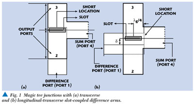
Two basic observations were used to develop the concept in designing the component. Analysis of waveguide-to-waveguide coupling through a transverse slot located in the common broadwall of two collinear waveguides and a longitudinal offset slot located in the common broadwall of two orthogonal waveguides6,7 have shown that a signal supplied to the first waveguide (port 1) can be coupled equally in magnitude and 180° out of phase to the two arms (ports 2 and 3) of the second waveguide. These facts have been used in designing the difference ports of two hybrids.
In addition, it has been observed, and can be qualitatively explained, that two waveguides, which are mutually parallel or perpendicular, cannot be coupled significantly through a narrow slot aperture if the slot is along the central axis of the feeding waveguide. This mechanism was used to decouple the sum and difference ports.
DESIGN OF PMTJ1 AND PMTJ2
The design of the magic tee (PMTJ1) has been carried out in stages. In the first stage, a MoM analysis of rectangular waveguide-to-waveguide coupling through a transverse slot (called a series-series slot) has been carried out. The slot due to its finite wall thickness has been treated as a rectangular cavity. An incident TE10 mode wave excites longitudinal magnetic current on the lower and upper slot apertures whose magnitude is not known. The magnetic field scattered in the waveguide regions and in the cavity regions are found in the terms of these unknown longitudinal magnetic currents on the slot apertures. The tangential component of the magnetic fields along the length of the slot is matched, and integral equations, in terms of unknown longitudinal magnetic currents on the slot, are formulated. These integral equations are then solved using MoM to get the slot aperture field. The present analysis is more accurate compared to the earlier ones where, while evaluating the electric field, the integration and differentiation of the Green's function have been changed only for functions which are completely integrable. In the present case, the source and field co-ordinates are separated, and appropriate integration and differentiation have been carried out. Based on this analysis, the scattering characteristics of the coupler have been obtained over a range of waveguide and slot dimensions, and frequencies. For non-standard, similar or dissimilar waveguide slot couplers, the scattering parameters are modified to satisfy the power balance condition and a proper normalisation has been accomplished in terms of two waveguide dimensions and wave impedances to make the scattering matrix symmetrical. The MoM analysis developed has been validated theoretically by comparing it with the results available in the literature. The scattering parameters of the coupler have been obtained after assuming it is a four-port coupler.
To see the applicability of such a waveguide coupler as a 3 dB coupler, this four-port coupler can be represented as a three-port matrix with one port short-circuited. It is found that
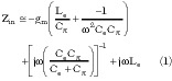
where the primed symbols represent scattering coefficients when one of the ports is short circuited (three port matrix) and unprimed symbols represents match terminated conditions (four-port matrix). After solving these two equations, it can easily be shown that

After solving this equation, it has been observed that full power coupling (S13 = S14 = 3 dB but 180° out of phase) is possible under certain conditions depending on the slot dimensions and short position with respect to the center of the slot. The resulting structure based on this analysis included ports designated by port 1 (difference arm), and ports 2 and 3 (output ports) for the junction PMTJ1.
In the second stage, arm 4 was attached to the waveguide containing ports 2 and 3 in the tee junction arrangement. The scattering characteristics of this H-plane septum-based waveguide tee junction (power divider) comprising the sum port (4) and two output ports (ports 2 and 3) were analysed using an FEM-based HFSS software package. This power divider uses two types of irises, first to split the incoming power from port 4 to ports 2 and 3, and the second to get a good input match at port 4. The size and position of these irises are critical.
In the final stage the two structures were combined to give a sum port, a difference port and two output ports. The scattering parameters of the structure are then deduced after analysing it using FEM-based CAD software. The size and location of the irises are optimised to obtain the required specifications. The optimization is done using HFSS CAD software by changing their dimensions and locations and computing scattering parameters through an iterative procedure until the required characteristics are achieved. Fine tuning of the slot and short location was also carried out to get the optimum performance.
To design the PMTJ2 magic tee junction, a similar MoM analysis of rectangular orthogonal waveguide-to-waveguide coupling through a longitudinal-transverse slot has been performed,7 and the scattering characteristics of the structure considering it as a four-port and three-port coupler have been obtained. By properly selecting the offset of the slot (*) from the center line of the difference arm and short circuiting the other port of the arm by putting a short at a quarter waveguide wave length from the center of the slot, the four-port coupler has been converted into a three-port coupler. At this optimized offset, the energy fed to port 1 gets coupled equally in amplitude (3 dB), but opposite in phase to ports 2 and 3. Similar procedures were used in designing PMTJ1 and PMTJ2.
COMPONENT RESPONSE
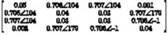
The design has been carried out for non-standard, reduced height waveguide dimensions to operate over a wide frequency range in Ku-band. The Ku-band frequency of operation has been chosen to demonstrate the technology for the cases where mechanical tolerances play a very important role. The scattering parameters of the components PMTJ1 and PMTJ2, obtained after designing, analysing and optimising the complete structure using MoM and FEM-based commercial software (HFSS), are given below for PMTJ1 and PMTJ2, respectively:
PMTJ1:
PMTJ2:
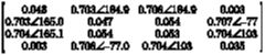
The following observations have been made: all the ports show a return loss better than 25 dB over a band of 500 MHz. The sum and difference ports are isolated from each other (isolation of the order of 50 dB and better). The output ports are isolated from each other (isolation better than 25 dB), and the amplitude and phase imbalance has been found to be negligible.
TWO PLANE MONOPULSE COMPARATOR NETWORK DESIGN
The monopulse comparator designed is a two layer waveguide network comprising three magic tee junctions (two PMTJ1 and one PMTJ1) and a H-plane tee junction, as shown in Figure 2. The working principle of the network giving sum and two orthogonal difference patterns are given below for the sake of clarity.

SUM CHANNEL NETWORK
The sum channel network is based on a septum-based H-plane tee junction as shown by dotted lines. The signal fed at the input port (sum port) gets divided equally (amplitude as well as phase) at junction 1, which gets further divided at junctions 2 and 3 exciting all the ports A, B, C and D in equal amplitude and phase, and thus giving the sum pattern.
DIFFERENCE CHANNEL NETWORK
The working of a difference channel network8 is based on the principle of a hybrid tee junction. Here a different approach has been adopted to realize this kind of compact network. The solid lines show the waveguide channels on one side, while the dotted line shows the waveguide channels on the other.
The signal fed at port El gets divided equally (amplitude as well as phase) at junction 4 (septum-based H-plane tee). At junction 2 the half signal is coupled to the other side of the waveguide through a slot (transverse slot) and divides equally in amplitude but opposite in phase. Thus port A and C are excited out of phase (quarter amplitude). Similarly at junction 3, the half signal is coupled to the other side of the waveguide through a transverse slot and is divided equally in amplitude but opposite in phase. Thus ports B and D are excited out of phase (but with quarter amplitude). Hence a signal fed at port El gets divided equally at all the ports with equal phase at ports A and B, while opposite phase at ports C and D giving the elevation difference pattern.
Similarly, a signal fed at Az port gets coupled to the other side of the waveguide through an offset slot with equal amplitude but opposite phase. Thus the signal reaching the H-plane tee junction 2 (at half amplitude) is divided equally, exciting ports A and C with a signal of quarter amplitude and same phase. The signal reaching the H-plane tee junction 3 is divided equally, thus exciting ports B and D with a signal of quarter amplitude but opposite phase. This gives the azimuth difference pattern.
EXPERIMENTAL VALIDATION
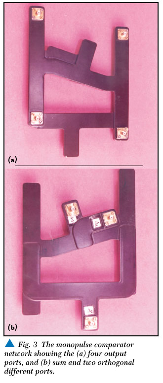
To verify the component experimentally, the design of a two-plane-monopulse-comparator network has been carried out using the following steps. (A photograph of the monopulse comparator network is shown in Figure 3.) First the designs of two types of magic tees were carried out for optimum performance, the results of which have been presented. Next an H-plane septum-based power divider (1:2) network is designed using HFSS. Afterwards the overall layout of the monopulse comparator network is completed by determining the output locations and other mechanical requirements. Accordingly, waveguide components such as different types of bends were designed for the best theoretical performance. These were added at appropriate positions to connect up the magic tees and power dividers. Additional lengths of waveguides were added wherever required to satisfy the phase requirement over the complete band of operation. Finally, the complete structure was reanalyzed using HFSS followed by reoptimization of the structure to obtain the required performance. All the ports, that is, the sum port, Az difference port, El difference port and four output ports, can either be realized in waveguide or in coaxial line. As non-standard waveguide dimensions are chosen in the present design, all the output ports are realized in coaxial. For this purpose a suitable non-standard waveguide to coaxial connector (SMA) adapter has been designed.
Extreme care has been taken in manufacturing the structure. The two layer structure has been realized by machining waveguide channels having septums, irises, slots and bends in a solid aluminium block, one side to form the sum signal channel, while on the other side of the block they are used to form the difference channels. The reduced height, non-standard waveguide dimensions (a = 11 mm and b = 2 mm) were chosen to make the component compact and lightweight. The two layers have a common wall thickness of 1.0 mm. A thin aluminum sheet covers the two sides of the structure. Required waveguide to coaxial adapters for all the ports are an integral part of the structure. The construction method uses standard adhesive and fixing systems, and thus, is most suitable for mass production.
The measured prototype had the following characteristics over 500 MHz bandwidth:
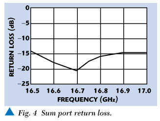
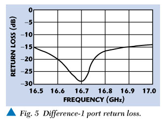
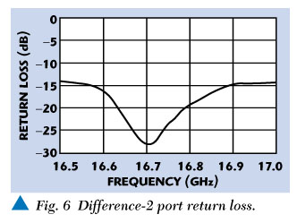
* Better than 1.5 SWR response in the sum and two difference ports; return loss better than 20 dB (SWR < 1.2) at the design frequency, as shown in Figures 4, 5 and 6.
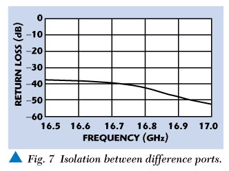
* Isolation between two orthogonal difference ports better than 38 dB over a band of 500 MHz, as shown in Figure 7.
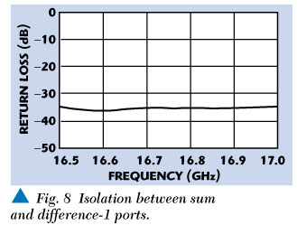
* Isolation between the sum and azimuth difference ports better than 35 dB over the band, as shown in Figure 8.
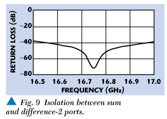
* Isolation between the sum and elevation difference ports of better than 38 dB over the band, as shown in Figure 9.
* With the excitation at the difference ports and signal measured at output ports, the phase difference was 180° with a maximum imbalance between output ports at 0.3 dB in magnitude and 2° in phase.
* When the sum port was fed, the phase difference was 0°, while the maximum imbalance between output ports was 0.3 dB in the magnitude and 3° in the phase.
* The size of the monopulse comparator network is approximately 130 mm * 130 mm * 7 mm, which can further be reduced depending upon a particular application.
|
|
|
|
|
|
|
|
|
CONCLUSION
A non-standard, reduced height compact waveguide magic tee junction has been designed using MoM and FEM-based CAD software. The scattering matrix of the component for the specified performance are deduced and used to design and develop a compact two plane monopulse comparator network for waveguide slotted array applications. *
References
1. Richard A. Sparks, "System Applications of Mechanically Scanned Slotted Array Antennas," Microwave Journal, June 1988.
2. S. Christopher and A.K. Singh, et al., "Design and Development of Planar Slotted Waveguide Array for Airborne Applications," Proceedings of Asia Pacific Microwave Conference, Korea, 1996.
3. S. Christopher, A.K. Singh and G.R. Rewankar, "A Low Cost, Lightweight, High Gain and Very Low Side Lobe Slotted Waveguide Array Antenna for Missile Applications," Proceedings of International Radar Symposium, India, IRSI-1999.
4. A.K. Singh and S. Christopher, "Computer Aided Design of High Performance Slotted Waveguide Array Antenna for Maritime Patrol Radar Applications," Proceedings of XIII International Conference on Microwaves, Radar and Wireless Communications, Poland, May 2224, 2000,
pp. 601604.
5. Hewlett-Packard, "High Frequency Structure Simulator," Software Package, Ver. 5.
6. A.K. Singh and S. Christopher, "Computer Aided Design of a Planar Magic Tee Junction for Slotted Waveguide Array Applications," Proceedings of Progress in Electromagnetic Research Symposium, Taiwan, 1999.
7. A.K. Singh and S. Christopher, "Moment Method Analysis of Longitudinal/Transverse Waveguide Slot Coupler," Proceedings of Progress in Electromagnetic Research Symposium, Hong Kong, 1997.
8. Samual M. Sherman, Monopulse Principles and Techniques, Artech House, 1984.
Dr. Anil Kumar Singh is a senior scientist in Electronics and Radar Development Establishment, Bangalore.
Dr. S. Christopher is additional director in Electronics and Radar Development Establishment, Bangalore.