
Achieving the dramatic jump in data rates for 5G’s enhanced mobile broadband service relies on the bandwidth available at mmWave frequencies. Dedicated spectrum in three bands-at 28, 39 and, more recently, 24 GHz-has been proposed, and regulatory authorities in many countries are allocating spectrum.
On the infrastructure side of the link, the development of mmWave base stations has progressed rapidly, enabled by field trials to determine propagation characteristics. Propagation has proven more resilient than many expected, benefiting from scattering and multipath. Using phased array antennas, base stations can provide the necessary EIRP and beam steering to achieve spatial coverage with the necessary link margins.
This early success has enabled companies like Verizon to begin deploying fixed wireless access services to stationary consumers, who mount 28 GHz antennas on windows or along roof lines. In most cases, subscribers can obtain respectable signal levels and data rates, as confirmed by an early independent evaluation in Houston by Signals Research Group.
The next big unknown has been the performance of a mobile smartphone at mmWave frequencies. Phone and component manufacturers face numerous technical challenges developing a viable mmWave radio for the phone:
- Ensuring antenna coverage regardless of phone orientation and hand placement.
- Maintaining sufficient link margins during transmit and receive.
- Maximizing phone battery life by minimizing power consumption.
- Minimizing the temperature rise of the module and phone with the thermal design.
- Minimizing the size of the mmWave radio, with a form factor compatible with a smartphone.
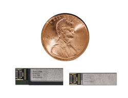
In July 2018, Qualcomm Technologies announced the QTM052 family of mmWave antenna modules for the smartphone-a first in the industry. Used with the Snapdragon X50 5G modem, the integrated system provides antenna to baseband processing and meets Release 15 of the 5G New Radio (NR) specification. Then, in October, Qualcomm added a new module design to the QTM052 family, reducing the size by 25 percent. The smaller design enables the module to be mounted along the edge of even thinner phones and supports up to four modules in a smartphone.
The QTM052 currently covers three 5G bands, handling up to 800 MHz aggregated carrier bandwidth in the 26.5 to 29.5 GHz band (n257) and covering the entire 27.5 to 28.35 GHz band (n261) and the entire 37 to 40 GHz band (n260). Functionally, the QTM052 comprises a phased array antenna, radio transceiver and power management. It connects to Qualcomm’s X50 5G modem, which controls beamforming and beam steering.
ANTENNA ARRAY
Various antenna options are available, supporting either face or edge placement in the phone. Qualcomm’s tests show that both orientations have similar performance, so the choice depends on other design trade-offs, such as phone thickness. Whichever configuration is used, several of the antenna modules are placed at different locations in the phone, ensuring coverage regardless of phone orientation and compensating for signal blockage when a hand is holding the phone (see Figure 1).

Figure 1 EM simulation of a mobile phone, showing mmWave signal attenuation caused by a hand holding the phone.
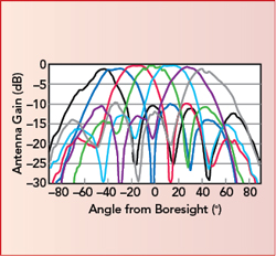
Figure 2 Antenna patterns of a vertically polarized patch array showing ±45 degree beam steering.
The arrays use patch and dipole antennas, either single or dual polarization. The arrays provide spherical coverage in each polarization and beam steering of ±45 degrees around boresight (see Figure 2).
TRANSCEIVER
The transceiver RFIC, fabricated with a silicon process, integrates transmit and receive channels for each antenna element, as well as providing frequency conversion between RF and IF. The on-chip up- and down-conversion includes the mixer, voltage-controlled oscillator with multiplier and phase-locked loop (see Figure 3).
The power amplifier can deliver 10 to 15 dBm output power, although it typically operates backed off to 6 to 8 dBm output to meet the 5G NR −25 dB error vector magnitude (EVM) linearity requirement. The transmit/receive (T/R) switch at the antenna is placed in the receive path, so it does not reduce output power. The input receive amplifier has a low noise figure which does not limit the performance of the downlink from base station to handset, even with the loss of the T/R switch. On-chip digital circuitry translates commands from the X50 modem to control the T/R state and the relative amplitude and phase of each antenna element. Beam steering and array taper are set with passive phase shifters and attenuators with 1 dB gain control steps, respectively.
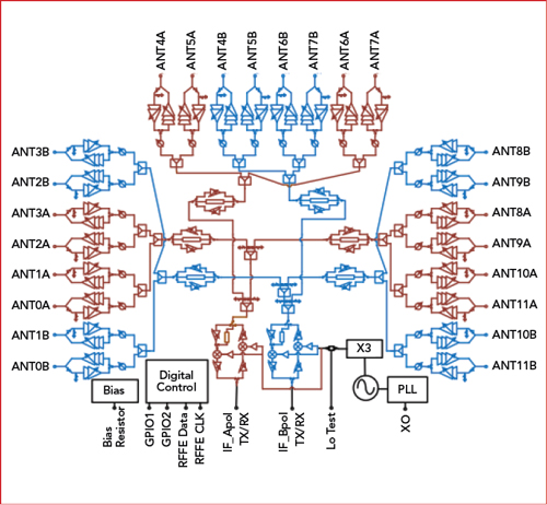
Figure 3 Notional block diagram of the transceiver RFIC.

Figure 4 The transceiver RFICs are mounted to the backside of the board containing the antenna arrays.
The transceiver RFICs are packaged in flip-chip ball grid arrays, which are mounted to the backside of the board containing the antenna array (see Figure 4).
EIRP AND POWER DISSIPATION
The shorter range of mmWave links, available output power from the power amplifiers and the constrained form factor of the phone challenged the design of the QTM052 to achieve the required output power and minimize power dissipation. As noted, the silicon power amplifier can deliver 10 to 15 dBm at 28 GHz. A single λ/2 patch antenna has a gain of 5 dBi, and a 2 x 2 array provides an additional 6 dB of summation gain and 6 dB beamforming gain. Using a single polarization adds another 3 dB, netting a total antenna gain of 20 dB, which boosts the radio output to 30 to 35 dBm EIRP.
The thermal design of the board holding the RFIC BGAs must channel the heat without creating “hot spots” in the phone noticeable to the user. For the 2 x 2 array transmitting a 64-QAM OFDM or SCFDM signal at 28 GHz, each power amplifier is backed off to approximately 6 to 8 dBm. At this output, the typical DC power dissipation for four transmit channels is 350 to 380 mW.
5G PHONES COMING SOON
Qualcomm has achieved an amazing engineering feat: developing a mmWave radio using a multi-polarization phased array antenna with beam steering and highly integrated RF transceiver that meets the 5G NR specification-a radio small enough so four modules will fit in a smartphone to ensure coverage while the phone is held. This level of engineering and end-to-end system integration in a commercial product is as impressive as the performance.
Operators and smartphone manufacturers say the first 5G phones will appear on the market in early 2019. Although Qualcomm will not say, no doubt you will find the QTM052 providing the mmWave connection.
Qualcomm Technologies Inc.
San Diego, Calif.
www.qualcomm.com