
Highly stable oscillators are key components in many important applications where coherent processing is performed for improved detection. The optoelectronic oscillator (OEO) exhibits low phase noise at microwave and mmWave frequencies, which is attractive for applications such as synthetic aperture radar, space communications, navigation and meteorology, as well as for communications carriers operating at frequencies above 10 GHz, with the advent of high data rate wireless for high speed data transmission. The conventional OEO suffers from a large number of unwanted, closely-spaced oscillation modes, large size and thermal drift. State-of-the-art performance is reported for X- and K-Band OEO synthesizers incorporating a novel forced technique of self-injection locking, double self phase-locking. This technique reduces phase noise both close-in and far-away from the carrier, while suppressing side modes observed in standard OEOs. As an example, frequency synthesizers at X-Band (8 to 12 GHz) and K-Band (16 to 24 GHz) are demonstrated, typically exhibiting phase noise at 10 kHz offset from the carrier better than −138 and −128 dBc/Hz, respectively. A fully integrated version of a forced tunable low phase noise OEO is also being developed for 5G applications, featuring reduced size and power consumption, less sensitivity to environmental effects and low cost.
Electronic oscillators generate low phase noise signals up to a few GHz but suffer phase noise degradation at higher frequencies, principally due to low Q-factor resonators. The conventional approach for high frequency signal generation is a frequency multiplier technique, but this suffers from higher phase noise due to AM-PM noise conversion1 and sub-harmonic generation.2 There are different types of resonators used in electronic oscillator circuits, such as printed coupled transmission line resonators using surface acoustic wave resonators, dielectric resonators, ceramic coaxial resonators, yttrium iron garnet (YIG) resonators and sapphire-loaded cavity (SLC) resonators. All have their unique characteristics and limitations. They typically operate from 500 MHz to 20 GHz; however, their Qs degrade as operating frequency increases and are, at best, limited to f × Q < 1014. SLC based oscillators offer low phase noise signal generation but have limited tuning capability and require precise low temperature cooling systems, which makes them expensive.

Figure 1 Typical metamaterial Möbius strips resonator: layout (a) and lumped circuit model (b).
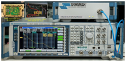
Figure 2 Phase noise measurement setup for the 10.24 GHz synthesizer using MMS inspired oscillator.
Emerging technologies focus on metamaterial resonator oscillators for microwave and mmWave applications.3 Efforts to improve phase noise performance and tuning range of metamaterial resonator oscillators led to the exploration of Möbius topologies for high frequency signal generation and signal processing.4 Figure 1 shows a typical layout of a printed Möbius metamaterial strips (MMS) resonator and its equivalent lumped LC circuit model. Figure 2 shows the phase noise measurement setup for an MMS inspired X-Band oscillator. The measured phase noise is −139 dBc/Hz at 10 kHz for a 10.24 GHz carrier (see Figure 3), where a narrow tuning range of about 5 percent is achieved with varactor diodes.4
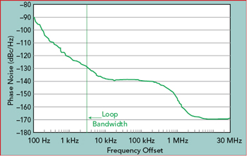
Figure 3 Measured phase noise of the 10.24 GHz synthesizer.
The novel approach for generating a low phase noise synthesized signal source demonstrated in Figures 1 through 3 trades phase noise for tuning and, therefore, is not suitable for wideband applications. The OEO offers a promising solution. It has a high Q-factor due to a long storage delay using low loss optical fiber, the potential for high frequency operation, due to inherently broadband electro-optic and optoelectronic transducers and a high immunity to electromagnetic interference.
CURRENT OEO TECHNOLOGY
A typical OEO is a hybrid electronic and microwave photonic system using an augmented positive feedback loop to facilitate low phase noise, high frequency signal generation. Yao and Maleki5-7 first reported microwave signal generation using optical fiber delay lines in 1996. Their methods, based on converting the continuous light energy from a pump laser to RF and microwave signals, may use optical fiber delay line or high Q optical resonators. The latter can utilize active or passive cavities. Low phase noise in a delay line oscillator is ensured by a high Q feedback loop using long, low loss optical fiber. The oscillation frequency is determined using a narrowband microwave filter.
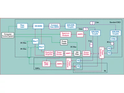
The OEO based on delay in an optical fiber loop suffers from multiple, closely-spaced oscillation modes that can pass through the narrowband microwave filter. To guarantee single-mode oscillation, an ultra-narrowband high Q microwave filter is needed, but such a filter is impossible to realize. Optical filtering could be incorporated, but filters that use optical resonators are difficult to implement and suffer from vibrational mode instability. Recently, Zhang and Yao8 reported single-mode operation without an ultra-narrowband optical filter based on parity-time (PT) symmetry and two identical matching feedback loops, with one having a gain and the other having a loss of the same magnitude. As shown in Figure 4, the PT-symmetric OEO utilizes polarization to implement tunable optical power splitting to the polarization sensitive balanced photo detector; however, even minor vibrations can stimulate strong modulation on the phase and polarization state of the light wave propagating in the long optical loop.

Figure 4 Block diagram of the PT-symmetric OEO.8
The measured phase noise plots reported by Zhang et al.,8 as illustrated in Figure 5, compare the performance of the PT-symmetric OEO to a state-of-the-art commercially available electronically generated microwave signal source. The PT-symmetric OEO operates with three different loop lengths (20.31 m, 433.1 m and 9.166 km). Phase noise at 10 kHz offset from the 9.76 GHz carrier frequency is typically −93, −104 and −143 dBc/Hz, respectively. It is interesting to note that the PT-symmetric OEO topology improves phase noise performance at 10 kHz offset from the carrier but significantly degrades close-in performance compared to commercial available signal sources. Significant side modes exist due to resonance conditions associated with the 9.166 km delay line. These side modes degrade oscillator timing jitters, even though they are reduced close-in to the carrier.
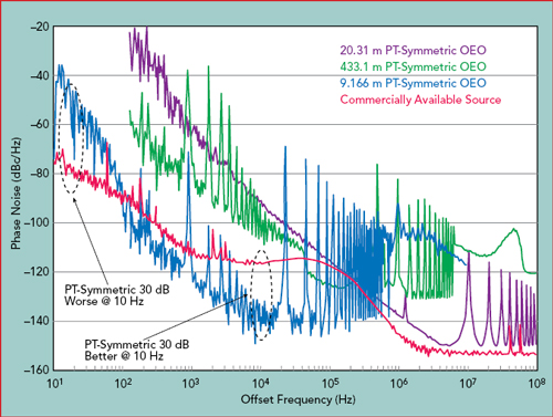
Figure 5 Phase noise of the PT-symmetric OEO vs. a commercially available source, both at 9.76 GHz.8
The suggested method to mitigate the poor close-in phase noise performances in a PT-symmetric OEO is to incorporate a polarization-insensitive optical power splitter and electrical feedback loop, to detect phase and polarization changes and perform real-time dynamic compensation. This can partially improve close-in phase noise performance; however, offsets greater than 10 kHz suffer degradation, and the approach lacks broadband tenability as well.
Current and future generation communication systems demand high frequency signal sources with tuning features to meet the criteria for broad bandwidth and high data transmission rates. The work described here offers solutions based on forced self-injection locking, double self phase-locking (SILDPLL) techniques.
SILDPLL OEO Synthesizers
Oscillator phase noise reduction can be achieved through injection locking (IL)9 and phase-locked loops (PLL).10 While IL is easy to implement, phase noise close to the carrier is degraded due to frequency detuning and a limited locking range.11 On the other hand, a high gain loop filter enables the PLL to remove close-in phase noise significantly, while far-away offsets suffer from a higher noise. Sturzebecher et al.12 demonstrated that in externally-forced oscillators, better phase noise characteristics for both close-in and far-away offset frequencies and a wider locking range are achieved by combining IL and PLL techniques. External reference sources are required, however, in the conventional injection locking phase-locked loop (ILPLL) topology, which limits the ultimate phase noise performance.
To bypass limitations imposed by an extremely stable external reference requirement, self-injection locking (SIL)13 and the self phase-locked loops (SPLL)14 have been proposed. SIL and SPLL are essentially feedback control loops where part of the output signal is delayed and used as the reference signal, eliminating the need for an external reference. The loop gain can be greatly enhanced in self-injection locking phase-locked loops (SILPLL) compared to SIL or SPLL alone, providing greater phase noise reduction. For long fiber delays, a large number of closely-spaced side modes at Δf = 200 kHz-km/L, where L is the fiber length in km, are expected in the forced oscillator spectra (as seen in Figure 5). Therefore, multiple feedback paths are introduced to cancel these side modes by using SILPLL, SILDPLL (two paths) and SILTPLL (three paths), depending upon requirements for side-mode suppression and corresponding timing jitter.

Figure 6 SILDPLL synthesizer block diagram.
Figure 6 shows the block diagram of an SILDPLL OEO synthesizer. It uses SIL and double-sideband PLL techniques to minimize phase noise close-in and far-out from the carrier. A low relative intensity noise (RIN) fiber laser (TWL-C-HP-M) is used to provide a wavelength-tunable laser signal. The signal is transmitted through an optical fiber delay line, received by a photo detector (DSC50S) and passed through a narrow band filter. The narrowband filter is the core of the OEO and is used to select the oscillation frequency. In this work, a tunable YIG filter is used for wideband operation and for coarse tuning of the frequency synthesizer. Further improvement is achieved by incorporating a narrowband optical transversal filter realized with a chirped fiber Bragg grating (CFBG)15-18 to provide narrowband microwave signal filtering. The optical transversal filter is wavelength dependent and provides frequency tuning as the wavelength of the fiber laser is tuned.
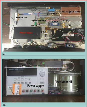
Figure 7 Top (a) and front view (b) of the X/K-Band SILDIL OEO synthesizer.
Besides the optical frequency selectivity of the YIG and optical transversal filter, SIL,14 SPLL15 and their combination SILPLL19 are applied to reduce synthesizer phase noise, both close-in and far-out from the carrier. Figure 6 shows the SIL and DSPLL.20-21 There are two paths for the modulated signal after the Mach-Zehnder modulator (MZM). One is the main loop of the OEO, and the other loop is split into two, creating 3 and 8 km dual phase-locking signals. The combined phase-locking signal is then input to a custom-designed mixer and lowpass filter amplifier (LPFA) board (see Figure 7). A double balanced mixer is integrated on this board with the LPFA, realized using opamp circuits, to work as a phase detector and lowpass portion of the PLL. The phase error of the OEO main loop is compared with the dual delay lines of the PLL, and the phase error signal is fed back to the bias port of the MZM. The SIL signal takes advantage of the PLL path and shares the same 3 km fiber used in the SPLL path. Dual delay lines of 3 and 8 km provide significant side-mode suppression. The 3 km SIL signal is tapped from one PLL signal and directly injected into the power combiner. The injected power level is expressed as

with Pi the injected signal power and Po the OEO power level.
The novelty of this approach is reflected in the design, implementation and testing of high frequency and resolution, 19-in. rack-mountable, X- and K-Band frequency synthesizers using SILDPLL OEOs. High resolution tuning is due to fine tuning of an optical transversal filter using a chirped fiber Bragg grating (CFBG) as a dispersive component for narrowband filtering. Second harmonic22 generation is achieved by biasing the dual-drive MZM close to Vπ to generate half rectified optical pulses. Performance of this synthesizer is evaluated by its measured close-to-carrier phase noise and its long-term frequency stability over 60 minutes with a maximum frequency drift of 4 kHz.
SILDPLL OEO Synthesizer Design

Figure 8 Phase noise measurement setup.
The frequency synthesizer, shown in the block diagram of Figure 6 and the hardware of Figure 7, uses SIL and double-sideband PLL techniques simultaneously, with multiple signal paths supporting enhanced signal stability, as well as the application of modulation as needed. Signals are combined within the synthesizer with the aid of a custom-designed double balanced frequency mixer and LPFA assembly. The synthesizer design also incorporates an opamp circuit that works as a phase detector and lowpass portion of the PLL. The high resolution and wavelength-sensitive tuning is due to fine tuning by wavelength control of the fiber laser used as the optical source for the extremely narrowband optical transversal filter. The optical filter uses a CFBG as a dispersive component to achieve narrowband filtering. A current-tuned YIG filter used in cascade with the optical filter and CFBG provides coarse frequency tuning across wide tuning ranges in X- and K-Band. At X-Band, for example, the YIG filter tunes with a response of about 25 MHz/mA. Since the resolution of the current supply feeding the YIG filter is about 1 mA, the effective frequency tuning resolution of the YIG filter is 25 MHz. This combination of optical and electronic technologies results in relatively wide frequency tuning ranges with outstanding phase noise, both close-in and far-out from the carrier. A higher frequency tuning resolution and narrowband filtering is achieved by the dispersive CFBG transversal filter, as opposed to a fiber based filter.23