
DIGITAL vs. ANALOG BEAMFORMING
Most AESAs that have been designed in past years use analog beamforming, where the phase adjustment occurs at the RF or IF frequencies, with only one set of data converters for the entire antenna. There is increased interest in digital beamforming, which uses one set of data converters at each antenna element, with the phase adjustment done digitally in the FPGA or data converter. Digital beamforming offers many benefits, starting with the ability to easily transmit many beams or change the number of beams almost instantly. This remarkable flexibility is attractive in many applications, which is driving adoption. Continuous improvements in the data converters—lowering power dissipation and expanding to higher frequencies, e.g., RF sampling at L- and S-Band—are making this technology a reality in radar systems.
Choosing between analog and digital beamforming requires multiple considerations, with the analysis usually driven by the number of beams required, power dissipation and cost targets. With a data converter at each element, the digital beamforming approach typically has higher power dissipation but offers flexibility in creating multiple beams. The data converters in digital beamforming must have greater dynamic range, since the beamforming that rejects blockers is done after digitization.
Analog beamforming can support multiple beams, however, it requires an additional phase adjustment channel per beam. Creating a 100-beam system, for example, multiplies the number of RF phase shifters by 100 compared to a single beam system. So the cost tradeoff between data converters and phase shifter ICs will depend on the number of beams required by the application.
Similarly, power dissipation is usually lower for an analog beamforming architecture that uses passive phase shifters; as the number of beams increases, the power dissipation will increase if additional gain stages are needed to drive the distribution network. A common compromise is hybrid beamforming, with sub-arrays of analog beamforming followed by digital combining of the sub-array signals. This is an area of growing interest and will continue to evolve.
Semiconductor technology
A standard pulsed radar system transmits a signal which eventually reflects off one or more objects. The radar waits for the return pulses to map the field of view of the antenna. In prior generations, the radar front-end (see Figure 4) would use discrete components, likely fabricated in GaAs. The front-end comprises a phase shifter to adjust the phase of each antenna element and steer the antenna, an attenuator to taper the beam, a power amplifier (PA) to increase the power of the transmit signal, a low noise amplifier (LNA) to boost the receive signal and a switch to toggle between transmit (Tx) and receive (Rx). In past implementations, each of these ICs could be in a 5 mm × 5 mm package; more advanced solutions would have an integrated, single channel GaAs MMIC to achieve this functionality.
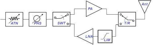
Figure 4 Typical RF front-end for a phased array antenna.
The recent proliferation of phased array antennas has been enabled by advances in semiconductor technology. The advanced nodes in SiGe BiCMOS, silicon on insulator and bulk CMOS enable the digital circuitry, used to control the steering of the beam, to be integrated with the RF, which performs phase and amplitude adjustment, in a single IC. It is possible to achieve multi-channel beamforming ICs for gain and phase adjustment, from four channels for lower frequency systems to 32 channels for mmWave designs. In some lower power applications, a silicon IC can monolithically integrate all these functions. In high-power applications, GaN PAs have significantly increased the power density sufficiently to fit into the unit cell of a phased array antenna, which traditionally would have been served by traveling wave tube (TWT) PAs or lower power GaAs PAs.
In airborne applications, the trend is toward flat panel architectures adopting the power-added efficiency (PAE) benefits of GaN technology. GaN has also enabled large ground-based radars to move to AESAs from traditional dish antennas driven by TWTs. Monolithic GaN ICs are capable of delivering greater than 100 W of power with over 50 percent PAE. Combining this level of PAE with the low duty cycle of radar applications enables surface-mount solutions to be feasible, greatly reducing the size, weight and cost of the antenna array. An additional benefit beyond the pure power capability of GaN is the size reduction compared to existing GaAs MMIC solutions. A GaN PA replacing a 6 to 8 W GaAs PA at X-Band reduces the footprint by 50 percent or more—very significant when trying to fit the electronics into the unit cell of a phased array antenna.
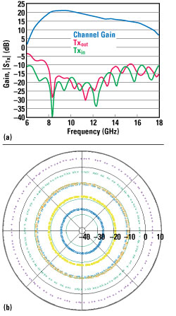
Figure 5 Transmit channel gain and match (a) and phase and gain control contours (b) of the ADAR1000 at 11.5 GHz.
ANALOG PHASED ARRAY ICs
Analog Devices, among other companies, has developed integrated analog beamforming ICs aimed at a range of phased array applications, including radar, SATCOM and 5G. As one example of current technology and capability, Analog Devices’ ADAR1000 X-/Ku-Band beamforming IC covers 8 to 16 GHz, which makes it well-suited for X-Band radar and Ku-Band SATCOM applications. The four-channel device operates in time-division duplex mode, with the Tx and Rx integrated into a single IC, which can be configured to operate in Tx- or Rx-only mode. The four channels are integrated in a 7 mm × 7 mm QFN surface-mount package, compatible with integration into flat panel arrays. The IC dissipates only 240 mW per channel in Tx mode, 160 mW per channel in Rx. The Tx and Rx channels are designed to mate with a front-end module, such as those offered by Analog Devices.
Figure 5 shows the ADAR1000’s gain and phase performance. It provides full 360 degree phase coverage with phase steps less than 2.8 degrees and greater than 31 dB gain control. The device contains on-chip memory to store up to 121 beam states, where one state contains all the phase and gain settings for the entire IC. The transmitter delivers approximately 15 dBm of saturated output power with 19 dB gain. Receive gain is approximately 14 dB. Phase variation with gain control is approximately 3 degrees over 20 dB of gain control range. Similarly, the gain variation with phase control is approximately 0.25 dB over the entire 360 phase coverage. This tight distribution simplifies array calibration.
SUMMARY
The availability of beamforming ICs is accelerating the adoption of analog and hybrid phased array architectures. Complementary improvements in front-end PA/LNA/switch modules, frequency conversion, data converters and digital signal processing are transforming the AESA, improving the performance and SWaP-C of military systems and enabling their use for commercial SATCOM and wireless systems applications.